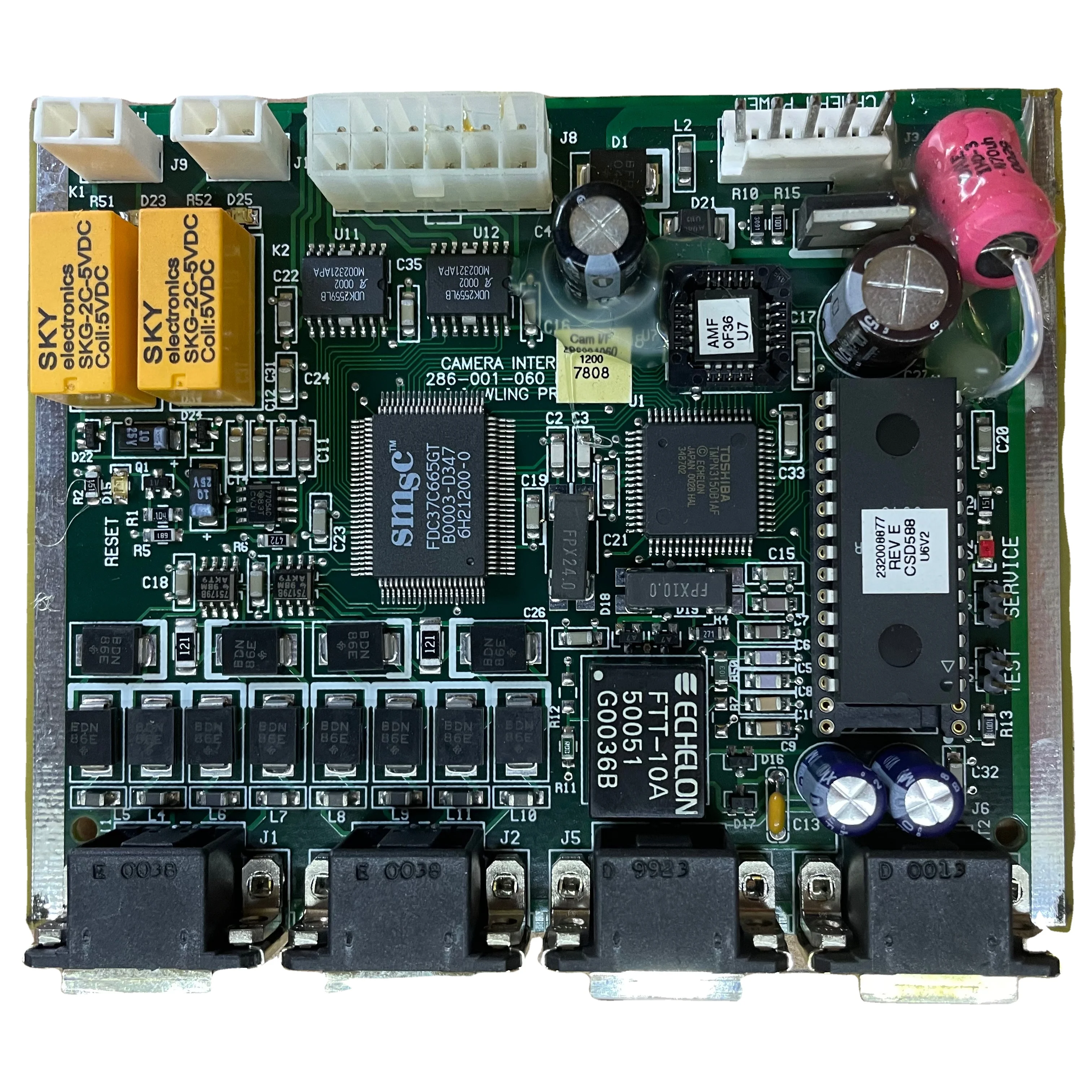
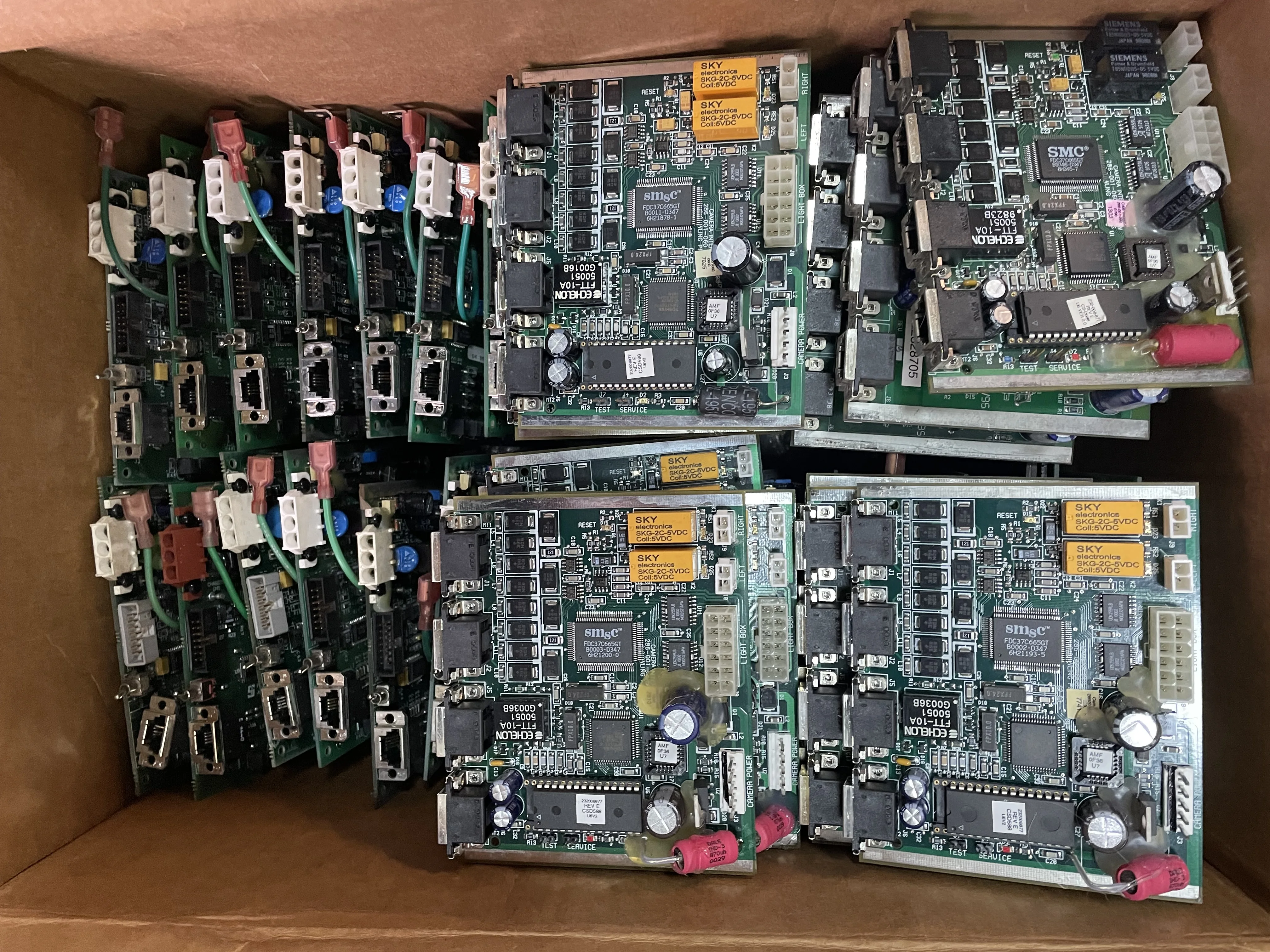
AMF BOSS Underline Camera Interface
- Category: >>>
- Supplier: Bowling Market & CO - FZCO
Share on (11000007547159):
Product Overview
Description
BOSS Underlane Camera
The camera sits on the wide coverboard ahead of the lanes and detects what pins are left standing after each ball.

5.2 MOUNTING THE PINSENSOR (continued)
2. FIND the range that corresponds to distance "A". SELECT the corresponding distance "B", which is the distance from the center of the 7 - 10 pin line to the back of the pinsensor.
Table Pinsensor Location Table
"A" distance
28" - 29"
29.5" - 30"
30.5" - 31"
31.5" - 32"
"B".
"B" distance
157" - 157.5"
158" - 158.5"
159" - 159.5"
161" - 161.5"
4. CENTER the drill template on the ball return capping so that the back of the pinsensor is at distance "B".
NOTE: For standard ball return capping material, the #31 drill bit and #10 sheet metal screws should be used. For thinner wood or metal capping, #10 machine screws or bolts should be used.
5. Using the drill template, DRILL four pilot holes in the ball return capping for the pinsensor chassis and four holes for the cover.
6. Using #10-32 mounting screws and washers, SECURE pinsensor to the capping.
7. ATTACH the power cable assembly from the Machine Interface to the AccuCam and the camera interface.
8. ATTACH the internal communication cable to the interface board and to the AccuCam.
9. ATTACH the camera lane communication cable from the Machine Interface to the communication port on the camera.
We Recommend
New Arrivals
New products from manufacturers at wholesale prices