
hydraulic rotary actuators manufacturer in china
- Category: >>>
- Supplier: Weihai Kaite Hydraulic Technology Co. Ltd.
Share on (1600339066489):
Product Overview
Description


KT30 SERIES PERFORMANCE
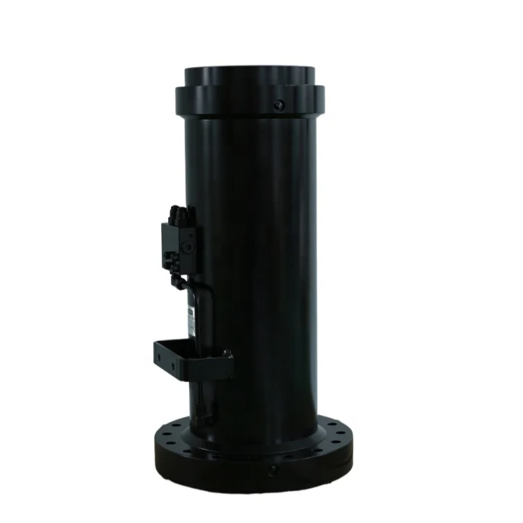
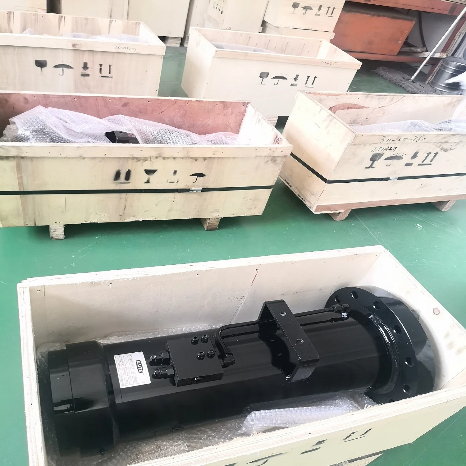
This helical hydraulic rotary actuator delivers power and performance in a compact size
to help you work in the tightest applications, it works stable and easy maintenance.
KT30 series actuators are available in a variety of standard configurations in 180 or 360 degree rotation.
KT30 SERIES PARAMETER | ||||||||||||||||
型号/model | 19 | 28 | 47 | 73 | 105 | 140 | 180 | 240 | ||||||||
输出扭矩/ Drive Torque Nm@21MPa | 1900 | 2800 | 4700 | 7300 | 10500 | 14000 | 18000 | 24000 | ||||||||
保持扭矩/ Holding Torque Nm@21MPa | 4900 | 6800 | 12000 | 18000 | 26000 | 35000 | 46000 | 59000 | ||||||||
悬臂安装弯矩/ Max cantilever moment Nm | 5200 | 7100 | 11900 | 18400 | 29500 | 38800 | 55900 | 72900 | ||||||||
跨式安装弯矩/ Max straddle moment (180° ) | 13400 | 16900 | 30800 | 47800 | 75100 | 98900 | 130500 | 170000 | ||||||||
跨式安装弯矩/ Max straddle moment (360° ) | 19200 | 24600 | 45400 | 71200 | 111500 | 146000 | 197700 | 256500 | ||||||||
径向负载/ Radial load kg | 1800 | 2300 | 3600 | 5000 | 6800 | 8200 | 10000 | 11800 | ||||||||
轴向负载/ Axial capacity kg | 1400 | 1800 | 2700 | 3600 | 4500 | 5900 | 6800 | 8200 | ||||||||
排量/Displacement 180° cc | 492 | 688 | 1180 | 1870 | 2680 | 3540 | 4650 | 6000 | ||||||||
排量/Displacement 360°cc | 980 | 1390 | 2360 | 3740 | 5360 | 7080 | 9320 | 12000 | ||||||||
重量/ Weight 180°)kg | 34.5 | 50 | 72.5 | 110 | 160 | 220 | 280 | 360 | ||||||||
重量/ Weight(360°)kg | 45.5 | 63.4 | 100 | 140 | 200 | 290 | 370 | 455 | ||||||||
D1 安装盘直径/ mounting dia mm | 139 | 155 | 183 | 209 | 234 | 263 | 288 | 310 | ||||||||
D2 壳体直径/ housing dia mm | 140 | 152 | 178 | 203 | 229 | 254 | 279 | 305 | ||||||||
F1 法兰端螺丝孔尺寸/ tap hole mm | M12×1.75 | M16×2 | M20×2.5 | M22×2.5 | M24×3 | M27×3 | M27×3 | M30×3.5 | ||||||||
F2 法兰端螺丝孔个数/ Nos of tap holes | 12 | 12 | 12 | 12 | 12 | 12 | 12 | 12 | ||||||||
F3 法兰端螺丝中心圆直径/ Pitch of mounting mm | 115 | 125 | 150 | 170 | 195 | 215 | 240 | 255 | ||||||||
F4 端盖端螺栓孔尺寸/ flange tap hole mm | M10×1.5 | M12×1.75 | M16×2 | M20×2.5 | M22×2.5 | M24×3 | M27×3 | M27×3 | ||||||||
F5 端盖端螺丝数量/ tap Nos | 12 | 12 | 12 | 12 | 12 | 12 | 12 | 12 | ||||||||
F6 端盖端螺丝孔中心圆直径/ pitch of tap holes mm | 108 | 120 | 133 | 150 | 170 | 190 | 210 | 230 | ||||||||
F7 安装孔直径/ Dia of mounting hole mm | M16 | M20 | M22 | M24 | M27 | M30 | M36 | M36 | ||||||||
H1 不含平衡阀高度/ height without counterbalance valve mm | 156 | 186 | 212 | 240 | 276 | 305 | 327 | 362 | ||||||||
H2 底面距中心线高/ center height mm | 80 | 94.9 | 108 | 122 | 140 | 154 | 165 | 184 | ||||||||
H3 底脚高/ foot height mm | 48 | 70 | 78 | 88 | 105 | 110 | 120 | 135 | ||||||||
H4 总高度/ overall height mm | 179 | 201 | 226 | 271 | 283 | 310 | 334 | 366 | ||||||||
L1总长度/ overall length(180°)mm | 298 | 323 | 365 | 413 | 475 | 524 | 551 | 600 | ||||||||
L1总长度/ overall length(360°)mm | 427 | 470 | 538 | 615 | 705 | 776 | 836 | 906 | ||||||||
L2不含旋转法兰长度/ length without flange(180°)mm | 261 | 286 | 323 | 363 | 431 | 463 | 493 | 534 | ||||||||
不含旋转法兰长度L2/ length without flange(360°)mm | 392 | 433 | 496 | 565 | 661 | 715 | 775 | 843 | ||||||||
法兰与平衡阀距离L3/ distance between flange and counterbalance valve(180°)mm | 75.2 | 134 | 143 | 130 | 152 | 185 | 196 | 221 | ||||||||
法兰与平衡阀距离L3/ distance between flange and counterbalance valve(360°)mm | 149 | 157 | 197 | 232 | 267 | 308 | 338 | 374 | ||||||||
底脚安装孔距L4/ mounting length(180°)mm | 229 | 248 | 281 | 314 | 374 | 400 | 426 | 460 | ||||||||
底脚安装孔距L4/ mounting length(360°)mm | 358 | 395 | 454 | 516 | 604 | 652 | 708 | 766 | ||||||||
法兰与安装孔距离L5/ Flange to mounting hole(180°)mm | 38.1 | 43.9 | 50 | 56.9 | 59.9 | 74.2 | 75.9 | 80 | ||||||||
W1 底脚安装孔距/ mounting width mm | 190 | 230 | 260 | 300 | 340 | 380 | 410 | 450 | ||||||||
W2 总宽度/ overall width mm | 222 | 268 | 310 | 350 | 400 | 447 | 484 | 530 | ||||||||
P1 P2 壳体油口/ port from housing | ISO-1179-1/BSPP‘G’, 1/8 "~ 1/4",see details in drawing。 | |||||||||||||||
V1 V2 阀体油口/ port from valve | ISO-1179-1/BSPP‘G’, 3/8",see details in drawing。 | |||||||||||||||

COMPACT DIMENSIONS
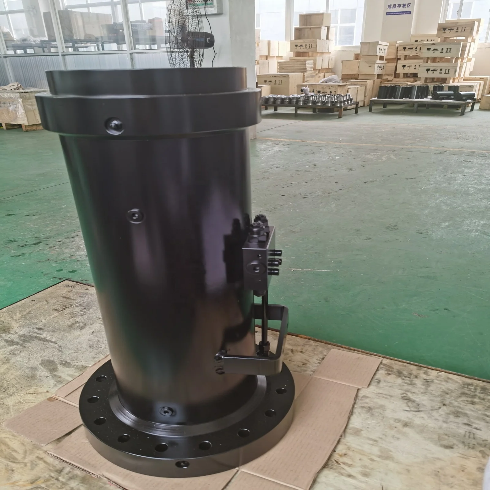
RIGID BODY
SAFETY FRAME
EASY CONTROL
EASY MAINTENANCE
CUSTOMIZED DESIGH AVAIABLE

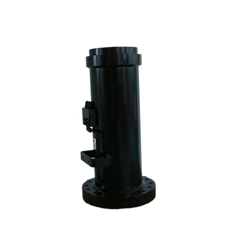
Flange mounting
Foot mounting
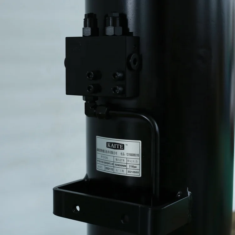
actuator with counterbalance valve
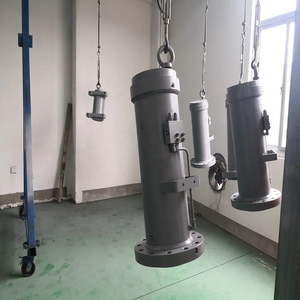
Quality control
Qulity control
prepare for assembly

Construction equipment
Aerial work platform
Fire fighting truck


Q1: Are you trading company or manufacturer ?
A:We are factory, all work done by us from design, manufacture, sales and service.
Q2: How long is your delivery time?
A: Generally it is 10 days if the goods are in stock. or it is 30~45 days if the goods are not in stock since advance paymen received, the specific delivery time depends on the items, transportation ways and the quantity of your order or if it need custom design.
Q3: What is your terms of payment?
A:Payment<=5000USD, 100% in advance. Payment>=5000USD, 30% T/T in advance, balance before shipment.
Q4. Can you produce according to the samples?
A: Yes, we can produce by your samples or technical drawings or special design as per customer demand.
Q5. Do you test all your goods before delivery?
A: Yes, we have 100% test before delivery
Q6. How about your quality warranty?
A:we promise one year warranty since products received, on line support available in case some question.

We Recommend


New Arrivals
New products from manufacturers at wholesale prices


