
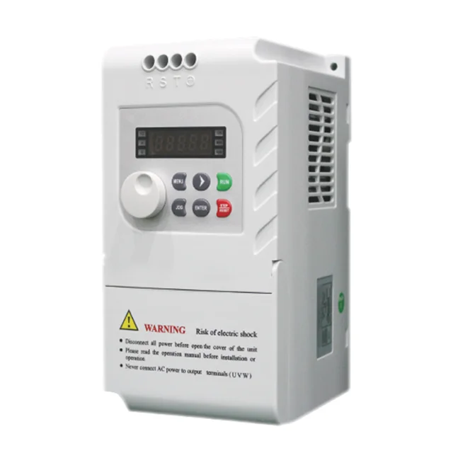
SiRON M10 New series Frequency Converter Universal Frequency Converter Heavy and light two types of load
- Category: >>>
- Supplier: Shenzhen Siron Electrical Co. Ltd.
Share on (1600342145602):
Product Overview
Description

Our company's product categories are very rich
Features
* Excellent control performance under speed sensorless vector control, truly realizing normal operation after power failure;
* Vector control under low frequency large torque stable operation, unique power grid instantaneous power down without shutdown, torque control operation;
* Energy-saving operation, automatic voltage adjustment (AVR) when the grid voltage changes, can automatically keep the output voltage constant.
* Vector control under low frequency large torque stable operation, unique power grid instantaneous power down without shutdown, torque control operation;
* Energy-saving operation, automatic voltage adjustment (AVR) when the grid voltage changes, can automatically keep the output voltage constant.
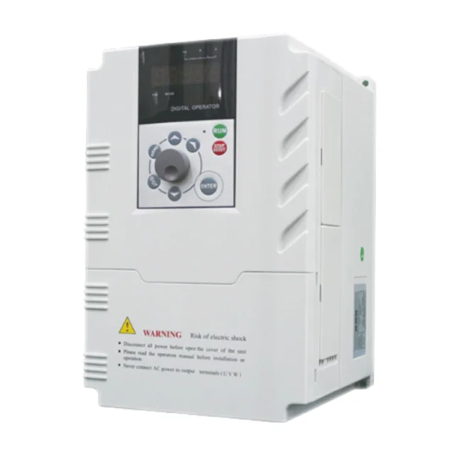
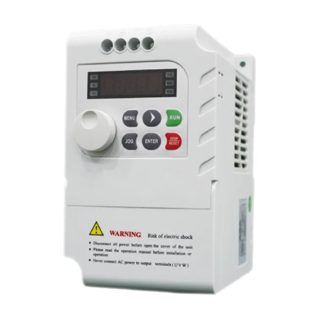
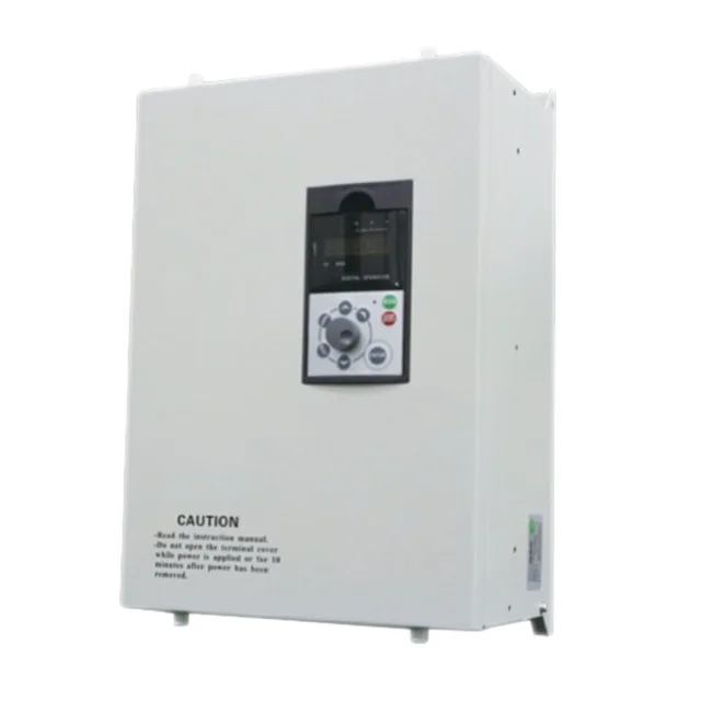
Products Description
Product Parameters
Project | Specification | ||||||
Output | Rated output voltage | 0~rated input voltage | |||||
Rated output current | According to the model | ||||||
Output frequency | 0.00~600.00Hz | ||||||
Maximum overload capacity | 150% for 1 minute, 200% for 1 second | ||||||
power supply | Rated input voltage | Three-phase/single-phase 220V Three-phase 380V ±10% 50~60Hz±5% | |||||
Control and operation | Self-adjusting output voltage | When the AVR function is valid, when the input voltage changes, the output voltage remains basically unchanged | |||||
way to control | Open loop vector control (SVC), V/F control, open loop torque control | ||||||
Speed range | 1:100 | ||||||
Output frequency resolution | Digital setting: 0.01Hz; analog setting: maximum frequency value x0.1% | ||||||
Voltage/frequency characteristics | There are two VF curves to choose from | ||||||
Torque boost | Automatic torque boost, you can also manually set the low-frequency torque boost | ||||||
Acceleration and deceleration characteristics | 0.1 second ~ 3600 seconds | ||||||
Frequency setting input | Keyboard, computer, 0~10V, 0~20mA | ||||||
Input command signal | Operation, forward/reverse rotation, jog, multi-speed, multi-speed acceleration and deceleration time, free stop, step control, reset, voltage/current signal input switch | ||||||
Standard function | Automatic fault retry, automatic torque boost, DC braking, restart after instantaneous power failure, frequency upper and lower limit limits, deviation frequency, frequency gain, carrier frequency adjustment, adjustable acceleration and deceleration mode, frequency meter and ammeter output, multi-speed, PID control, RS-485 interface, Modbus communication protocol | ||||||
Protective function | Overvoltage, undervoltage, phase loss, current, current limit, overheating, electronic thermal overload relay, overvoltage stall, data protection | ||||||
External output signal | Fault relay number, 0~10V, 0~20mA voltage and current signal | ||||||
Project | Specification | ||||||
Display | keyboard | Parameter setting | Function code, data, status, etc. | ||||
Operation monitoring | |||||||
Fault display | |||||||
Conditions of Use | Installation site | Indoor, the altitude is less than 1 km, no dust, no corrosive gas and no direct sunlight | |||||
Applicable environment | -10°C ~ +40°C (please use derating when +40°C ~ 50°C), 20% ~ 90%RH (non-condensing) | ||||||
vibration | Less than 5.9m/S2(0.6g) | ||||||
Storage method | -25°C〜+ 65° C | ||||||
Installation method | Wall-mounted | ||||||
Protection level | Less than 7.5kw is IP20, above 11kw is IP10 | ||||||
Cooling method | Forced air cooling | ||||||
Main circuit terminal | ||||||||
Terminal label | Description | |||||||
R/L1、S/L2、T/L3 | AC power input terminal, connected to three-phase AC power or single-phase AC power | |||||||
U、V、W | Inverter output terminal, connected to three-phase AC motor | |||||||
+、- | The connection terminals + and-of the external braking unit are the positive and negative poles of the DC bus respectively | |||||||
P/+、PB | Braking resistor connection terminal, one end of the braking resistor is connected to P/+, the other end is connected to PB | |||||||
+、P1 | External DC reactor terminal, one end of the reactor is connected to +, the other end is connected to P1 | |||||||
PE | Ground terminal, connect to the earth | |||||||

External keyboard dimensions


Recommend Products
Company Profile


Certifications

Delivery

FAQ
1.What type of company are you?
We are a manufacturer, we have stock of most of products and we support customization.
2.What can you buy from us?
Terminal Block Module, Relay Module, Cable, LED Light, Sensor,
Control Power Box Body, Push Button, Switch, and Auxiliary
Equipment, Human Machine Interface, Frequency Converter, Servo
Motor, Module, Reducer and Other Industrial Automation Control Products.
Please contact us if you do not find the product you want.
3.How about the quality of the products?
We can provide one year warranty for you and we have the
certification of CE, CCC, UL, and RoHs etc.
we could send the certification test of our company to you.
4.How do you make our business long-term and good relationship?
We have agents in Thailand, Japan, Singapore, Vietnam and South
Kore.a... and we do hope you become our agent in the future,
welcome to discuss the deep details with us.
We Recommend


New Arrivals
New products from manufacturers at wholesale prices


