
1920x720 Winstar IPS 12.3 inch TFT Display 1920x720 with PCAP supporting LVDS Interface 1920x720
- Category: >>>
- Supplier: Wuxi Siminuo Technology Co. Ltd.
Share on (1600379701082):
Product Overview
Description
Dear customers,
For more details or more related products, pls feel free to browse our website as follow:
//www.simair-lcd.com/
If you need any help, you may contact us at any time on the website. We are glad to serve you.
DESCRIPTION
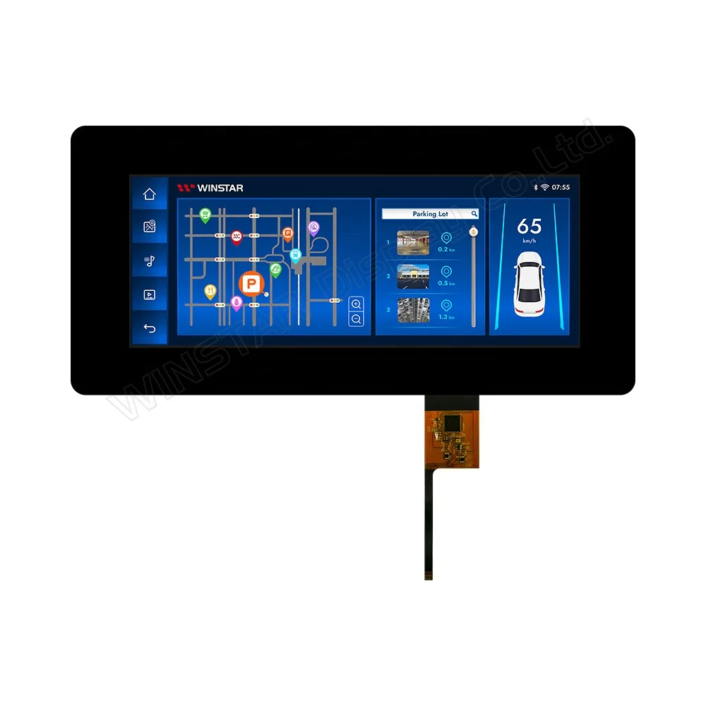
WF123BSWAYLNB0 is a 12.3 inch High Brightness 1920 x 720 IPS TFT-LCD module with projected capacitive touch panel (PCAP). This module supports 2-ch LVDS(Low-Voltage-Differential-Signaling)interface which becomes more popular for larger size of TFT LCD display. The LVDS interface is a great solution because of its high speed of data transmission while using low voltage and improved noise performance. The LVDS interface has several benefits for TFT displays. It is much less susceptible to EMI and crosstalk issues, and peripherals in need of high bandwidth, like high-definition graphics and fast frame rates, allowing the transmitting device to be located farther from the display. As to the capacitive touch panel of this module is built-in with ILI2511 IC which can communicate via USB or I2C interface, supports 10 detect points.
WF123BSWAYLNB0 is adopted IPS panel which is having the advantage of wider view angle of Left:85 / Right:85 / Up:85 / Down:85 degree (typical value), contrast ratio 1100:1 (typical value), brightness 650 nits (typical value), glare surface panel. The supply voltage (VCC) of WF123BSWAYLNB0 is from 3V to 3.6V, typical value 3.3V. It can be operated at wide temperatures from -30℃ to +85℃ and storage temperatures from -40℃ to +85℃. If customers require wider storage temperatures up to -40℃ to +90℃, you can choose our WF123BSWAYLNBA. Please note, the thickness of these two modules is a little different, WF123BSWAYLNB0 is 10.48mm, and WF123BSWAYLNBA is 10.7mm.
DRAWING

SPECIFICATIONS
Interface
TFT LCD Module
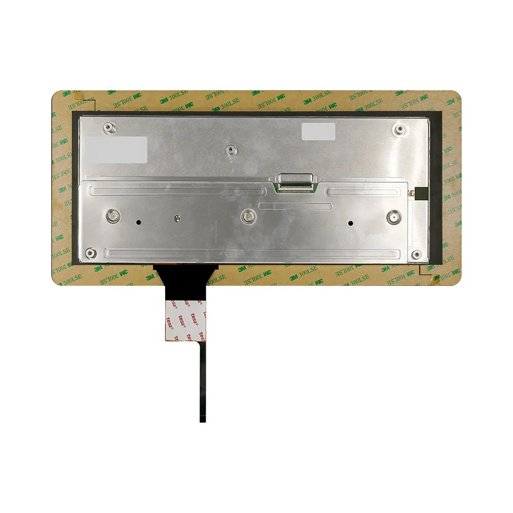
FPC connector is used for electronics interface.
AORORA F31L-1A7H1-21050 , 50PIN
| Pin no. | Symbol | Function |
|---|---|---|
| 1 | GND | Ground |
| 2 | NC | No connector |
| 3 | VCC | Digital Power |
| 4 | VCC | Digital Power |
| 5 | GND | Panel Power |
| 6 | GND | Panel Power |
| 7 | NC | No connector |
| 8 | NC | No connector |
| 9 | GND | Ground |
| 10 | ORXIN0- | Odd pixel negative LVDS differential clock input |
| 11 | ORXIN0+ | Odd pixel positive LVDS differential clock input |
| 12 | ORXIN1- | Odd pixel negative LVDS differential clock input |
| 13 | ORXIN1+ | Odd pixel positive LVDS differential clock input |
| 14 | ORXIN2- | Odd pixel negative LVDS differential clock input |
| 15 | ORXIN2+ | Odd pixel positive LVDS differential clock input |
| 16 | ORXCLKIN- | Odd pixel negative LVDS differential clock input |
| 17 | ORXCLKIN+ | Odd pixel positive LVDS differential clock input |
| 18 | ORXIN3- | Odd pixel negative LVDS differential clock input |
| 19 | ORXIN3+ | Odd pixel positive LVDS differential clock input |
| 20 | ERXIN0- | Even pixel negative LVDS differential clock input |
| 21 | ERXIN0+ | Even pixel positive LVDS differential clock input |
| 22 | ERXIN1- | Even pixel negative LVDS differential clock input |
| 23 | ERXIN1+ | Even pixel positive LVDS differential clock input |
| 24 | ERXIN2- | Even pixel negative LVDS differential clock input |
| 25 | ERXIN2+ | Even pixel positive LVDS differential clock input |
| 26 | ERXCLKIN- | Even pixel negative LVDS differential clock input |
| 27 | ERXCLKIN+ | Even pixel positive LVDS differential clock input |
| 28 | ERXIN3- | Even pixel negative LVDS differential clock input |
| 29 | ERXIN3+ | Even pixel positive LVDS differential clock input |
| 30 | GND | Ground |
| 31 | NC | No connector |
| 32 | RESETB | Global reset pin, active low. |
| 33 | STBYB | Standby mode, active low. |
| 34 | CA3 | Output signal to indicate self protection mode, when DE,HS,VS,DCLK, any of these signals is missing, it will become High. If using this pin, CA3 need to pulled low by an resistor,else , let it floating. |
| 35 | SCL | Serial interface clock input. (User folating) |
| 36 | SDA | Serial interface data input/output.(User folating) |
| 37 | CSB | Serial interface chip enable.(User folating) |
| 38 | GND | Power Ground |
| 39 | GND | Power Ground |
PCAP PIN Definition
| Pin | Symbol | Function |
|---|---|---|
| 1 | USB_VSS | System ground |
| 2 | USB_VDD 5V | Power supply |
| 3 | USB_D+ | Data + |
| 4 | USB_D- | Data - |
| 5 | VSS | System ground |
| 6 | SDA | I2C data input and output |
| 7 | SCL | I2C clock input |
| 8 | RST | External Reset, Low is active |
| 9 | INT | External interrupt to the host |
| 10 | VDDT 3.3 | Power supply |
General Specifications
| Item | Dimension | Unit |
|---|---|---|
| Size | 12.3 | inch |
| Pixel Number | 1920 RGB (H) × 720(V) | pixel |
| Module dimension | 364.0(H) × 175.0 (V) × 10.48 | mm |
| Active Area | 292.032(H) × 109.512(V) | mm |
| Pixel Pitch | 0.1521(H) × 0.1521 (V) | mm |
| LCD type | TFT, Normally Black, Transmissive | |
| Viewing Angle | 85/85/85/85 | |
| Backlight Type | LED ,Normally White | |
| TFT Interface | 2ch-LVDS | |
| PCAP IC | ILI2511 or equivalent | |
| PCAP Interface | USB (I2C available) | |
| PCAP FW Version | V6.0.0.0.0.0.0.3 | |
| Touch Panel | Projected Capacitive Touch Screen, PCAP | |
| Surface | Glare | |
We Recommend


New Arrivals
New products from manufacturers at wholesale prices


