
Инфракрасный модуль обхода препятствий, датчик/переключатель 38 кГц 2 120 см, регулируемый
- Category: Development Systems, and IoT Products >>>
- Supplier: Shenzhen Chipskey Technology Co. Limited
Share on (1600384272623):
Product Overview
Description
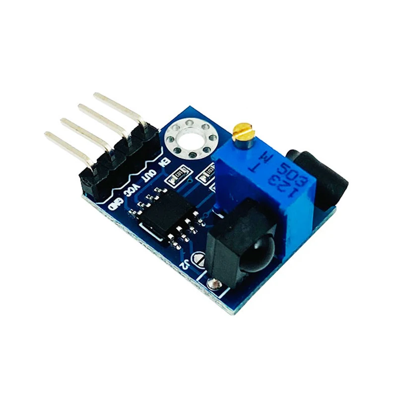
Infrared obstacle avoidance module sensor/switch 38KHz 2-120CM adjustable
Working voltage: 3.8v-5.5v
Working current (at 5V): typical current 6ma
Infrared 38KHz obstacle avoidance module enhanced anti-jamming version (KC-S80009)
product description
Non-logic chip oscillation frequency adjustment 38KHz detection circuit. This infrared 38KHZ obstacle avoidance module can completely block the detection distance of traditional photoelectric obstacle avoidance and the single normally open or normally closed signal output function and cannot avoid the infrared light interference of the radio or remote control of the same module.
Features
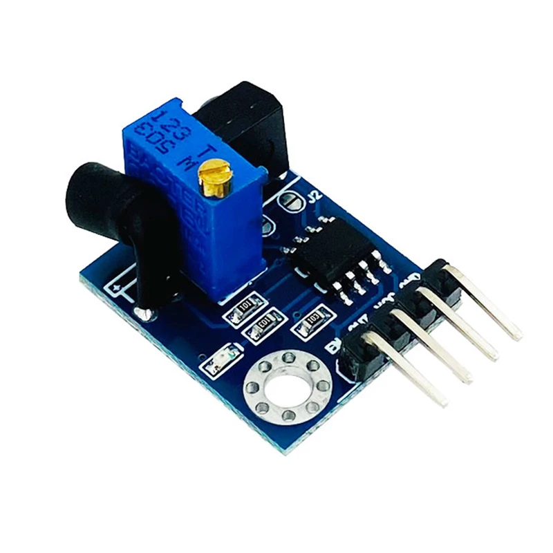
A variety of installation and welding methods, vertical and horizontal, expand the scope of application
Add a precision potentiometer to adjust the infrared 38KHz detection range
Sensor detection with enable port, convenient for signal line as a bus application line
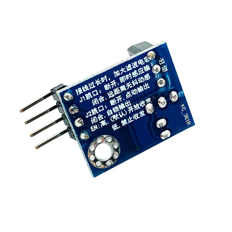
The power-on enable port defaults to high level, and the sensor is enabled to detect the output signal
The detection range can reach 1.2 meters away
The software is enhanced, and the settings can avoid the infrared light interference of the same type of module or other types of infrared remote control equipment
Use EEPROM to record the working status of each module, reducing the probability of mutual interference of the same model to 1%
Signal low level output
Pin SIP header, used in breadboard or through-hole projects
The jumper JP is set on the board, the signal output has a latch function when it is short-circuited, otherwise it is a jog output
Main specifications
Power requirements: 5 VDC
Communication: digital high/low output
Operating temperature: 32 to 158°F (0 to +70°C)
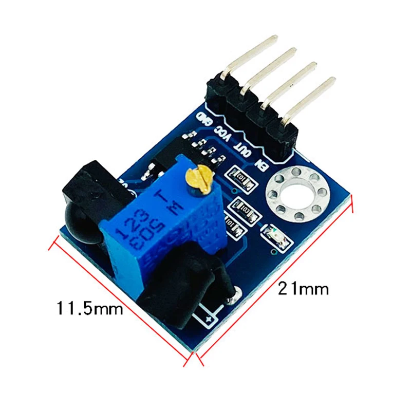
Size: 2.1cm×1.75cm
Application creativity
Warehouse door control lighting switch (lock setting)
Security trigger alarm system
Automatic production line conveyor belt object count
Robot control etc.
Signal output enable pin
Sensitivity
The maximum detection distance of the infrared 38KHz obstacle avoidance module is 2 meters. However, if you use the sensor in this area to trigger false readings under the current environmental factors, you can adjust the on-board potentiometer within this range to shorten the detection range. Stable (latch) receiving distance of 1.2 meters.
Pin description
Work Attention and Phenomenon
The black heat shrinkable tube on the outer layer of the infrared emitting tube is very useful, and the infrared emitting tube must be tightly wrapped, otherwise the diffusely reflected infrared light will interfere with the infrared receiving head and directly affect the signal output. The transmitter head only needs to expose the exact center point of the transmitter, so that the emission angle of the infrared transmitter tube can be reduced, and the obstacles in front can be effectively detected at a long distance to prevent and reduce interference.
After power on, the red LED on the board will flash 3 times and enter the working state. When an obstacle is detected in the front distance, the red LED on the board will light up, otherwise the industry will go out, and the SIG pin will output a low-level signal, and the EN pin must be high-level. The EN pin is high by default, which enables the sensor to work. If the JP tin bridge on the board is short-circuited, when an obstacle is detected in the front for the first time, the red LED on the board will light up, and the SIG will output low level at the same time, until the obstacle disappears, the red LED and SIG pin will output The signal is evenly latched in the previous state, that is, it remains lit and low-level signal output; when an obstacle is detected for the second time (even times), the red light on the board goes out, and the SIG changes to a high-level signal output. The latched state does not change until the third time (odd number of times) is detected.
This version of the 38KHZ obstacle avoidance module solves the interference of the same or similar infrared light remote control. Compared with the previous version, the red part of the article is the updated part.
The function test procedure for the use of the enabled port is as follows
/************************************************
* Program name: Enable use of infrared photoelectric obstacle avoidance module *
* MCU: STC89C52RC *
* OSC: 12MHz *
* WDT: DIS *
* Compiler software: μVision V4.00a *
* Editor: Cao Yanhuan (KC_8023) *
* Time: 2013-03-12 *
*************************************************/
#include
sbit LED = P1^0;//When there is an object in front of it, the indicator light is on at low level
sbit EN = P1^1;//Whether the infrared module is turned on for detection, the high level is valid
sbit SIG = P1^2;//Detect the low level of the infrared module and the low level is valid
void delay_nus(unsigned int i) //Delay: i>=12, the minimum delay order of i is 12 us
{
i=i/10;
while(--i);
}
void delay_nms(unsigned int n) //delay n ms
{
n=n+1;
while(--n)
delay_nus(900); //Delay 1ms and compensate at the same time
}
void main()
{
while(1)
{
EN = 1;//Enable infrared module detection
delay_nms(150);//Waiting for the detection processing time of the infrared obstacle avoidance module 150mS
if(SIG == 0)//When the infrared obstacle avoidance module outputs low level
LED = 0;//common anode connection
else
LED = 1;
EN = 0; //Turn off infrared module detection
delay_nms(400); //Indicator working time (that is, the module initiates a test every 400MS)
}
}
Working current (at 5V): typical current 6ma
Infrared 38KHz obstacle avoidance module enhanced anti-jamming version (KC-S80009)
product description
Non-logic chip oscillation frequency adjustment 38KHz detection circuit. This infrared 38KHZ obstacle avoidance module can completely block the detection distance of traditional photoelectric obstacle avoidance and the single normally open or normally closed signal output function and cannot avoid the infrared light interference of the radio or remote control of the same module.
Features
A variety of installation and welding methods, vertical and horizontal, expand the scope of application
Add a precision potentiometer to adjust the infrared 38KHz detection range
Sensor detection with enable port, convenient for signal line as a bus application line
The power-on enable port defaults to high level, and the sensor is enabled to detect the output signal
The detection range can reach 1.2 meters away
The software is enhanced, and the settings can avoid the infrared light interference of the same type of module or other types of infrared remote control equipment
Use EEPROM to record the working status of each module, reducing the probability of mutual interference of the same model to 1%
Signal low level output
Pin SIP header, used in breadboard or through-hole projects
The jumper JP is set on the board, the signal output has a latch function when it is short-circuited, otherwise it is a jog output
Main specifications
Power requirements: 5 VDC
Communication: digital high/low output
Operating temperature: 32 to 158°F (0 to +70°C)
Size: 2.1cm×1.75cm
Application creativity
Warehouse door control lighting switch (lock setting)
Security trigger alarm system
Automatic production line conveyor belt object count
Robot control etc.
Signal output enable pin
Sensitivity
The maximum detection distance of the infrared 38KHz obstacle avoidance module is 2 meters. However, if you use the sensor in this area to trigger false readings under the current environmental factors, you can adjust the on-board potentiometer within this range to shorten the detection range. Stable (latch) receiving distance of 1.2 meters.
Pin description
Work Attention and Phenomenon
The black heat shrinkable tube on the outer layer of the infrared emitting tube is very useful, and the infrared emitting tube must be tightly wrapped, otherwise the diffusely reflected infrared light will interfere with the infrared receiving head and directly affect the signal output. The transmitter head only needs to expose the exact center point of the transmitter, so that the emission angle of the infrared transmitter tube can be reduced, and the obstacles in front can be effectively detected at a long distance to prevent and reduce interference.
After power on, the red LED on the board will flash 3 times and enter the working state. When an obstacle is detected in the front distance, the red LED on the board will light up, otherwise the industry will go out, and the SIG pin will output a low-level signal, and the EN pin must be high-level. The EN pin is high by default, which enables the sensor to work. If the JP tin bridge on the board is short-circuited, when an obstacle is detected in the front for the first time, the red LED on the board will light up, and the SIG will output low level at the same time, until the obstacle disappears, the red LED and SIG pin will output The signal is evenly latched in the previous state, that is, it remains lit and low-level signal output; when an obstacle is detected for the second time (even times), the red light on the board goes out, and the SIG changes to a high-level signal output. The latched state does not change until the third time (odd number of times) is detected.
This version of the 38KHZ obstacle avoidance module solves the interference of the same or similar infrared light remote control. Compared with the previous version, the red part of the article is the updated part.
The function test procedure for the use of the enabled port is as follows
/************************************************
* Program name: Enable use of infrared photoelectric obstacle avoidance module *
* MCU: STC89C52RC *
* OSC: 12MHz *
* WDT: DIS *
* Compiler software: μVision V4.00a *
* Editor: Cao Yanhuan (KC_8023) *
* Time: 2013-03-12 *
*************************************************/
#include
sbit LED = P1^0;//When there is an object in front of it, the indicator light is on at low level
sbit EN = P1^1;//Whether the infrared module is turned on for detection, the high level is valid
sbit SIG = P1^2;//Detect the low level of the infrared module and the low level is valid
void delay_nus(unsigned int i) //Delay: i>=12, the minimum delay order of i is 12 us
{
i=i/10;
while(--i);
}
void delay_nms(unsigned int n) //delay n ms
{
n=n+1;
while(--n)
delay_nus(900); //Delay 1ms and compensate at the same time
}
void main()
{
while(1)
{
EN = 1;//Enable infrared module detection
delay_nms(150);//Waiting for the detection processing time of the infrared obstacle avoidance module 150mS
if(SIG == 0)//When the infrared obstacle avoidance module outputs low level
LED = 0;//common anode connection
else
LED = 1;
EN = 0; //Turn off infrared module detection
delay_nms(400); //Indicator working time (that is, the module initiates a test every 400MS)
}
}
We Recommend
PL2303 USB To RS232 TTL Converter Adapter Module
US $1.25-$5.00
DCS 1842 MHZ Saw Filter EFCH1842TCA7
US $0.10-$10.00

70cm 3Pin Male Jumper Wire Cable for 3D Printer
US $0.10-$2.00


50A H-bridge High-power Motor Driver module IBT-4
US $5.00-$8.00
New Arrivals
New products from manufacturers at wholesale prices


