


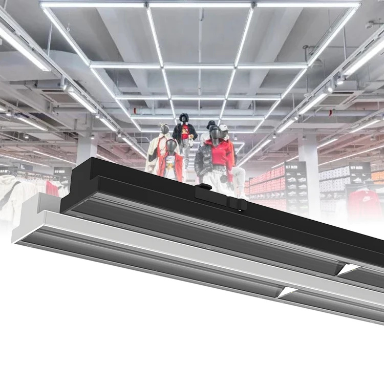
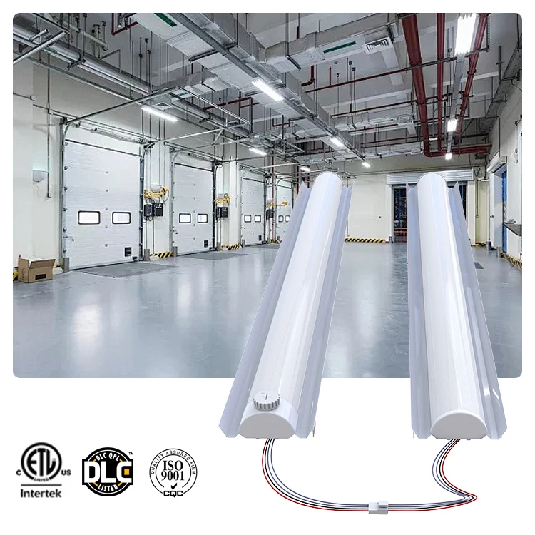
Combination with high bay sensors such as daylight and motion detection smart LED luminaires bring you task optimized lighting
- Category: >>>
- Supplier: Guangzhou Cheng Hong E-Tech Co. Ltd.Guangzhou Ltd.
Share on (1600466573820):
Product Overview
Description

Key Features:
1. Max. Control Qty. : 1,000 units LED high bay Light - share 1 Server, Cloud Based Datahub
2. PLC Line Comm : Exiting Power Lines( Cable/Cord/Wires) for Communication or Hybrid with wireless
3. Automatic Run : Turn On/Off, Sensoring Dimming according to the Nature Light Intensity/Ambient Light Sensors
4. Motion Sensors : Moving Object/ Forklift / Pedestrian
5. Auto-Reporting : Tempt/ Malfunctions/Loop Power
6. Power Metering : 3 phases Grid Data & Cabinet Monitoring / Power Consumption Report / Remote Energy Metering
Detailed Video showing /Dowload on YouTube & Google:
www.youtube.com/watch?v=KtKFD1a0qvY
www.stsystemplc.com
I. System Equipment Composition
3.2.1 Equipment Composition of the System
Server, workstation, on-site touch screen control, mobile(iPad) and other handheld devices, smart centralized controllers (or gateways), loop switch controllers, loop dimming controllers, single-lamp smart lighting management terminals, dual-lamp smart lighting management Terminal, dual-colors(2700K~6000K) intelligent lighting management terminal, dual-mode(hybrid of PLC+LoRa) intelligent lighting management terminal, multi-functional intelligent lighting management terminal, smart panel switch, illuminance meter (or brightness meter), motion sensor, linkage sensor, gas sensor, weather sensor, etc., and emergency Or supporting professional equipment (repeaters, copy controllers, monitors, debugging equipment, etc.).

Generally speaking, the system are divided into cloud management center equipment, human-machine interface equipment, local management center equipment, lighting fixture control equipment, sensor equipment, and debugging equipment.
3.2.2 Cloud Management Center Equipment
The core of cloud management center is system software, hardware carrier is server or server group. The cloud management center relies on the private cloud platform to collect the needed information, integrates through the big data component, uses the data collection, the data governance, the data warehouse, the data intelligence four big function modules to realize the concrete function.

Server--Software Monitor Center
Server is generally installed in the monitoring center and the core of the whole system. All the man-machine interface equipment access to the field equipment, long-term data storage ofthe field equipment, data statistical analysis and other related operations need to be coordinated and managed through the server, which is the link and bridge between the workstation, device and field equipment.

3.2.2 Human-machineInterfaceEquipment
On-Site Touch Screen Control
As a supplement to the workstation, simple operation and convenient installation location make the on-site touch control screen an indispensable part of the system.
The on-site touch control screen can operate independently from the cloud management center equipment to achieve the smallest control system; in the event of a cloud management

Mobile/IPAD Moving Control Device:
As a supplement to the workstation, simple operation and convenient installation location make the on-site touch control screen an indispensable part of the system.

Workstation:
A high-efficiency work platform with a friendly man-machine interface for workers in the field of industrial control applications.
Under the B/S architecture, the system supports parallel operation of multiple workstations (multi-users), which is flexible and convenient.

Handheld devices:
As a supplement to the workstation, simple operation and convenient installation location make the on-site touch control screen an indispensable part of the system.


Inspection panel switch:
In maintenance or emergency use, it can also replace the original circuit switch.

3.2.3 Local Management Center Equipment
As a management device connecting the previous and the next equipment,torealize the conversion of communication channels and the operation and management of local devices.
It is mainly used for loop dimming, multi-module integration, bus single-lamp controller control, etc.

Centralized controller CH-800:
As a management device connecting the previous and the next equipment, it realizes the conversion of communication channels and the operation and management of local devices.
Mainly used for energy consumption management, PLC single-lamp controller, wireless single-lamp controller control, Hybrid PLC + LoRa Controller, 2700-6000K CCT Auto Changing Single Lamp Controller.

Smart Gateway:
As a management device connecting the previous and the next equipment, it realizes the conversion of communication channels and the operation and management of local devices.
Mainly used for switch circuit control,loopdimming control, lamp dimming control, lamp colors control, sensors control, etc.

3.2.4 Management & Control Equipment Terminal
3.2.5.1 Loop control level equipment
CH-HC201:
The max. control current (resistive load) of each loop is 30A. Multiple loops can be correlated with each other and can operate according to input signals from multiple sensors, with loop fault detection.

CH-H0102:
Single-loop switch control, to controlthe 3-Phase power line, needs to be used with an ACContactor.
The maximum loop control current (resistive load) is 5A. Can be cascaded, with loop fault detection.

3.2.5 Single lamp control level equipment
Individual lamp controller:
CH-D0001,CH-D0002,CH-D0004,CH-D1001,CH-D1002,CH-D1006,CH-D2001,CH-D2002,CH-D2005,CH-D5001,CH-D5002,CH-D5004, CH- D7001, etc.
Switching,Dimming the single lamp according to different models,will choose Industrial Bus, LORA, NB-IoT,power line-communication, and other channels.
With multi-functions on Fault detection and reporting, such as: lamp failure, communication abnormality, power supply failure, led chip failure, high temperature, etc.And functions of collecting electric parameters and measuring electricenergy.
Dual-lamp controller,
Multi-lamps controller:
CH-D0601,CH-D1601,CH-D1606,CH-D260,CH-D5601,CH-D2604,CH-D7601,etc.
Same function asthesingle lamp controller, which can control two or more lamps at the same time.
Dimming &2700k~6000k CCTauto changingcontroller:
CH-D0201,CH-D0202,CH-D0204,CH-D120,CH-D1202,CH-D2201,CH-D2202,CH-D520,CH-D5204,CH-D7201:
On the basis of theindividual-lamp controller,addingthe function ofdual colors(2700~6000K) auto-changing in different environment.
Hybrid PLC+ LoRa Controller:
CH-D6001,CH-D6002,CH-D6004,CH-D7401, etc.:
On the basis of theindividual lamp controller, one or two communication channels are added to realize the simultaneous operation of multiple communication interfaces.
3.2.6 Signal Repeater & Debugging Equipment
A variety of Repeaters, Copy Controllers, Monitors, and Debugging Equipment.
II. Electrical Parameter
Item | Rating Range | |
Maximum Loading Lamp Qty. | 400 units(extend to1000 units, option for industry lighting) | |
Working Voltage | 120/240V±20%( Max.<420V) | |
Working Frequency | 50Hz - 60Hz | |
SwitchingOutput | 8A(MAX), Over-current Capacity (resistive load) | |
Insulation withstand voltage | 4KV, (RS485 interface and power supply) | |
Communication Channels | PLC, LoRa, or Hybrid of PLC + LoRa | |
Maximum Consumption Power | < 3 watts | |
Remote Control | Group & Individual ON/OFF/Dimming | |
Latitude & Longitude Switch | Yes | |
Lighting Sensors | Seamless Fill brightness by Illuminance Sensor + Motion Sensor | |
Scene Lighting Automatically | Rainy, Cloudy, Fogs, Snowing Days Auto-adjusting | |
Grid / Lamp Monitoring | V/I/W/PW, Active & Reactive Power, Lamp Tempt., Cabinet Door Status, Air quality PM2.5, Snow, Rain, Fogs etc. | |
Power Metering | Reporting & Analysis | |
GPRS Warning | Lamp Failure,Over Temperature/Voltage, Wires Stolen, GPS location the Stealing-electricity on google map. | |
Statistical Analysis | Luminance Ration, Alarm Statistics, Power Saving Ration, Voltage/Current Fluctuate, Environment Monitor | |
Protection | Automatic Shut down when Over Tempt. ; Location Stealing & Automatic Calculation of Power Stealing, Wire Stealing Alarm & Location, Decreasing Current Impact & Extend Lifetime. | |
Asset Management | Lower Budget can choose our Asset Managing System | |
Video Monitoring | CCTV Camera for safer city (option) | |
EV Charging | Option | |
Insulation withstand voltage | L/N-PE | 1.5KV |
L/N-485/DIM | 3.5KV | |
Surge Protect(L-N L-PE N-PE) | ±8KV | |
StaticElectricity | ±8KV | |
Operating Temperature | -25℃~+60℃ | |
Storage andWorkingHumidity | ≤85% | |
IP Rating | IP54 | |
Dimensions | 155x110*110mm (L/W/H) | |
Certifications | CE,ROHS | |
III: Key Featur
1. Indicator Description
2. Button Operation Instructions
1). Manual /Auto Run
Under Manual Status -The Dimming Button Operation on the panel is Effective, otherwise the operation is invalid.
Press the "Manual/Auto-Run" button to achieve manual / automatic state transition. That is to say, now it is Manual State, press again to enter the Auto-Run state.
When changing from Manual state to Automatic state, the equipment will automatically broadcast and issue Automatic Operation Recovery Command.
2). Controlling Button
No. | Button | Function |
01 | 100% | Send 100% dimming command to the selected loop |
02 | 75% | Send75% dimming command to the selected loop |
03 | 50% | Send50% dimming command to the selected loop |
04 | 25% | Send25% dimming command to the selected loop |
05 | Off | SendOff command to the selectedLoop (0% dimming) |
3. Lighting Controlling Functions
1). Control Priority Level
High priority or Same Level can change the state of low priority or same level, while low priority can not change the state of high priority.
The control mode corresponds to the following priorities.

2). Priority Level 1 - Recovery Auto-Run Operating (Highest Priority Level)
At this time, the state of priority Level 4 is executed regardless of the control state in which it was previously operated(the specific operation is performed according to the setting value at the time of installation).
a) The server or client remotely issues “Recovery Auto-Run” command.
b) Press the "Manual/Auto - Run" Button on the device panel
3). PriorityLevel2-LocalManualControl
Change the illuminance of the lamp through the control button on the device panel; at this time, the control commands of priority 3 and priority 4 will not be executed if the manual command is executed.
4). Priority Level 2-RemoteOperationControl
Remotely issue the controlCommands through the Server or the Client; at this time, the Lighting that executes theManual Command, the Priority Level 3 and Priority Level 4 control status will not be executed.
5). PriorityLevel3- IlluminationControl
Controls the Brightness values of all Fixtures according to preset rules by the received illuminance value.
6). PriorityLevel4 -Latitude&LongitudeControl
By setting the Latitude and Longitude values, the Sunrise and Sunset times are calculated, Disconnect the Loop at the sunrise time, Closed the Loop at the sunset time . The On-Off time can be fine-tuned by the Sunrise and Sunset offset time, and the range of fine-tuned for 30 minutes.
7). Priority Level 4 -ScheduleControl
Control the Brightness Value of the Fixture through the set 6-Segment Schedule.
4. DataCollection
Remote or Local Acquisition of Loop Controllers and Lamps Operating Status and Parameters.
5. ElectricalParameterAcquisition (Optional)
1).Collection ofElectricityConsumption
The device has a Built-in Three-Phase Energy Collection Module, which can collect the Energy Measurement Value of the Internal Module and Report it.
The Device can Collect the Energy Measurement Value of the Loop Controller and the Energy Meter and Report it.
2). ElectricalParameterAcquisition
The Built-in Three-Phase Energy Collection Module can collect the Voltage, Current, Active Power and Power Factor of the internal Module and Report it.
The Device can collect the Voltage, Current, Active Power and Power Factor of the Loop Controller, the Energy Meter and the Intelligent Lighting management Terminal, and Report it.
6. Fault Reporting
The Fault of the Device itself Occurs(AC Contactor Fault, Clock Fault, Communication Fault, etc.), and the Fault Information is automatically reported to the Server.
Collect the Information:such as Loop Controllers Fault and Light Controllers Fault, etc. (AC Contactor Faults, Clock Faults, Communication Faults, Lamp Faults, Temperature Faults, etc.)
7. DataCommunicationChannels
1) . PLC - Power Line Communication
Power Line Communication (PLC) is a communication technology that enables sending data over existing power cables. This means that, with just power cables running to an electronic device (for example) one can both power it up and at the same time control/retrieve data from it in a half-duplex manner.
2). LoRa Communication
Through LoRa Wireless Communication Channel, the Data Exchange and Control Command Reception between the Device and the Man-Machine Interface Device are realized. The Technical advantages are as follows:
a) Adopting the latest International IoT(Internet of Things) LoRaCommunication Technology, combined with AES128 Communication Encryption Technology and Self-Organizing Network Technology, the Communication Distance, Reliability and Security are greatly improved.
b) The Point-to-Point Communication Distance can reach 3,000m, and the measured average in the Power Plant is 1,000m.
c) In the case of Repeater, measured 13,000m can be normal communication.
3). RS-485 Communication
Through RS-485 Communication Channel, the Data Exchange and Control Command reception between the Device and the Man-Machine Interface Device are realized. The Technical Advantages are as follows:
a). The device capacity in the gateway is 255.
b). Strong Anti-Interference, Differential Mode Communication, and Software Fault Tolerance, no need to use Dedicated RS-485 Communication Line, reduce engineering cost under the premise of Ensuring Reliability
8. Extended Function (Optional)
1). Linkage
The Device can be linked with Equipment such as Cameras and Conveyer Belt; For example, when the Camera is activated, the Brightness of the Corresponding Lighting Area is Raised lighting the whole area, to Restore the Original Illumination when theCamera Stop Shooting; Another example, when the Conveyor Belt start transmission, its corresponding lighting area is adjusted the brightness, illuminates the area, and restores the minimum safe illuminance when Stop Transmission.
2). Dimming Loop Extension
The Control Loop can be concatenated to realize the application of Multiple Requirements.
VI: Soltutions-- PLC & LoRa

PLC ~ Power Line Communication

V: Widely application on the huge Projects


VI: Exhibitions Showing

We Recommend

New Arrivals
New products from manufacturers at wholesale prices