

LT BPI M1 Banana pi allwinner A20 Dual Core 1GB RAM on board WiFiCustom PCB smart face recognition main board pcba
- Category: >>>
- Supplier: Shenzhen Lonten Technology Co. Limited
Share on (1600472876216):
Product Overview
Description
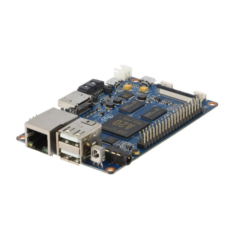
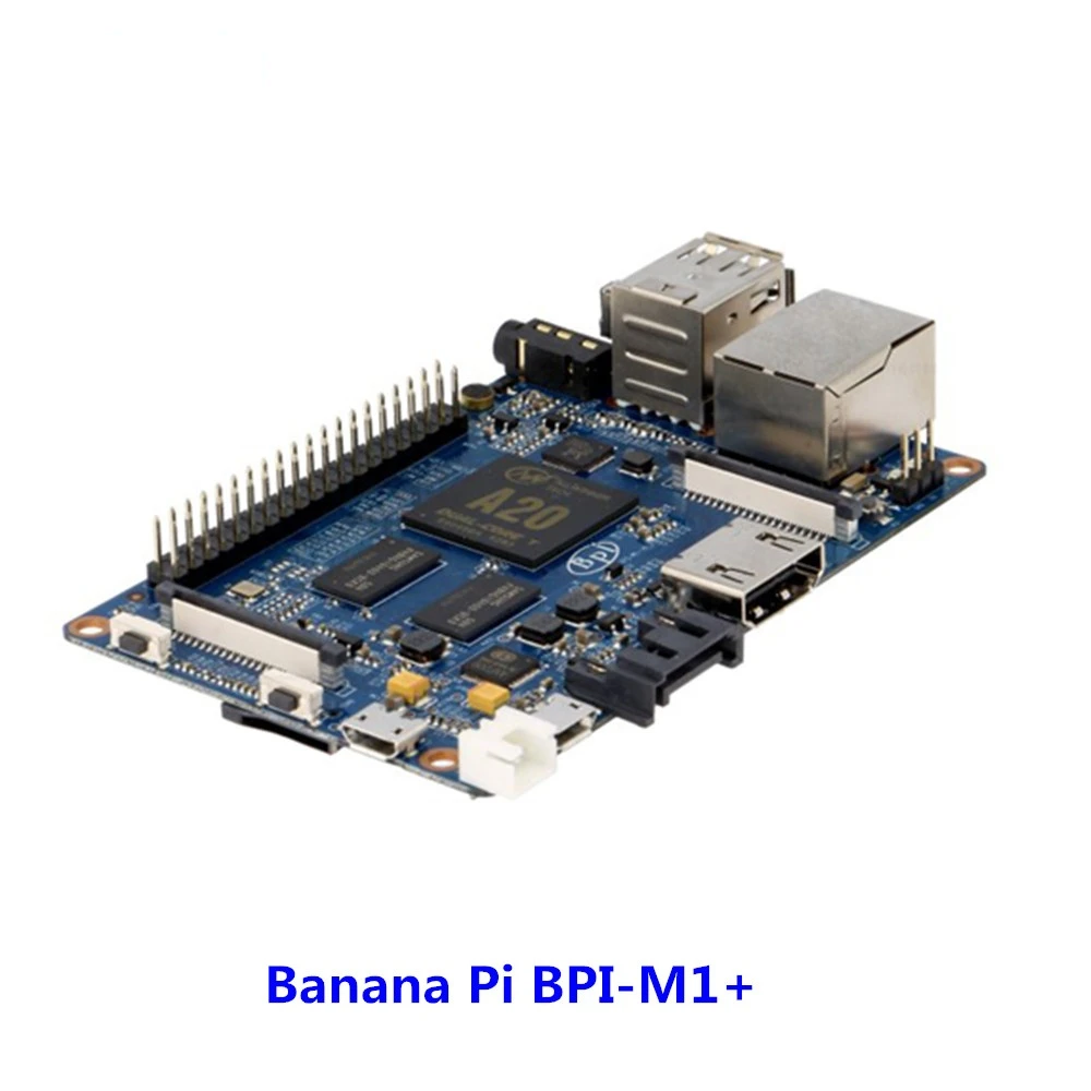
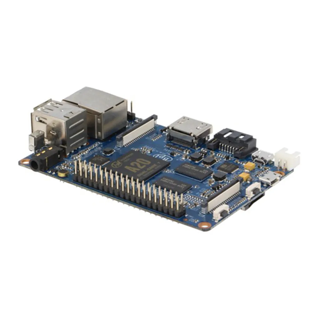
Banana Pi A20 BPI M1 Plus single board computer
This is singal board price ,if you need, you can choose accessories as follow :
BPI OV5640 camera, 7 inch touch screen, USB power connector (5V 2A)
Epacket logistics is expected to be 15-30 working days,and slow update of logistics informations, If you mind ,please choose the fast logistics channel . Thank you : )
Hardware
Hardware interfact

Hardware spec
| Banana Pi M1+ | |
|---|---|
| CPU | A20 ARM Cortex -A7 Dual-Core |
| GPU | ARM Mali400MP2Complies with OpenGL ES 2.0/1.1 |
| Memory | 1GB DDR3 |
| Network | 10/100/1000 Ethernet |
| wifi&BT | Wifi & BT 4.0 support onboard |
| Video Input | A CSI input connector allows for the connection of a designed camera module |
| Video Outputs | HDM1, CVBS, LVDS/RGB |
| Audio Outputs | 3.5mm jack and HDM1 |
| Power Source | 5V/2A via Micro USB (DC in only) and / or Micro USB OTG |
| USB 2.0 ports | 2(direct from Allwinner A20 chip) |
| GPIO | GPIO, UART, I2C BUS, SPI BUS, WITH TWO CHIP SELECTS, CAN bus, ADC, PWM, +3.3V, +5V, GND |
| LED | Power Key & 8P8C |
| Storage | SATA 2.0 |
| OS | Android 4.4, Android 4.2, Raspbian, Lubuntu, Open Suse, Debian |
| 40 PIN GPIO of Banana pi BPI-M1+ | |||
| GPIO Pin Name | Default Function | Function2:GPIO | |
| CON3-P01 | VCC-3V3 | ||
| CON3-P02 | VCC-DC | ||
| CON3-P03 | TWI2-SDA | PB21 | |
| CON3-P04 | VCC-DC | ||
| CON3-P05 | TWI2-SCK | PB20 | |
| CON3-P06 | GND | ||
| CON3-P07 | PWM1 | PI3 | |
| CON3-P08 | UART3\\_TX | PH0 | |
| CON3-P09 | GND | ||
| CON3-P10 | UART3\\_RX | PH1 | |
| CON3-P11 | UART2\\_RX | PI19 | |
| CON3-P12 | PH2 | PH2 | |
| CON3-P13 | UART2\\_TX | PI18 | |
| CON3-P14 | GND | ||
| CON3-P15 | UART2\\_CTS | PI17 | |
| CON3-P16 | CAN\\_TX | PH20 | |
| CON3-P17 | VCC-3V3 | ||
| CON3-P18 | CAN\\_RX | PH21 | |
| CON3-P19 | SPI0\\_MOSI | PI12 | |
| CON3-P20 | GND | ||
| CON3-P21 | SPI0\\_MISO | PI13 | |
| CON3-P22 | UART2\\_RTS | PI16 | |
| CON3-P23 | SPI0\\_CLK | PI11 | |
| CON3-P24 | SPI0\\_CS0 | PI10 | |
| CON3-P25 | GND | ||
| CON3-P26 | SPI0\\_CS1 | PI14 | |
| CON3-P27 | TWI3-SDA | PI1 | |
| CON3-P28 | TWI3-SCK | PI0 | |
| CON3-P29 | I2S\\_MCLK | PB5 | |
| CON3-P30 | GND | ||
| CON3-P31 | I2S\\_BCLK | PB6 | |
| CON3-P32 | I2S\\_DI | PB12 | |
| CON3-P33 | I2S\\_LRCK | PB7 | |
| CON3-P34 | GND | ||
| CON3-P35 | I2S\\_DO0 | PB8 | |
| CON3-P36 | UART7\\_RX | PI21 | |
| CON3-P37 | IR0\\_TX | PB3 | |
| CON3-P38 | UART7\\_TX | PI20 | |
| CON3-P39 | GND | ||
| CON3-P40 | SPDIF\\_DO | PB13 | |
CSI Camera Connector specification:
The CSI Camera Connector is a 40-pin FPC connector which can connect external camera module with proper signal pin mappings.The pin definitions of the CSI interface are shown as below. This is marked on the Banana Pi board as "CON1″.
| CSI PIN of Banana pi BPI-M1+ | |||
| CSI Pin Name | Default Function Pin name | Function2:GPIO | |
| CON1 P01 | LINEINL | ||
| CON1 P02 | LINEINR | ||
| CON1 P03 | VCC-CSI | ||
| CON1 P04 | ADC\\_X1 | ||
| CON1 P05 | GND | ||
| CON1 P06 | ADC\\_X2 | ||
| CON1 P07 | FMINL | ||
| CON1 P08 | ADC\\_Y1 | ||
| CON1 P09 | FMINR | ||
| CON1 P10 | ADC\\_Y2 | ||
| CON1 P11 | GND | ||
| CON1 P12 | CSI-FLASH | PH17 | |
| CON1 P13 | LRADC0 | ||
| CON1 P14 | TWI1-SDA | PB19 | |
| CON1 P15 | LRADC1 | ||
| CON1 P16 | TWI1-SCK | PB18 | |
| CON1 P17 | CSI-D0 | PE4 | |
| CON1 P18 | CSI0-STBY-EN | PH19 | |
| CON1 P19 | CSI0-D1 | PE5 | |
| CON1 P20 | CSI-PCLK | PE0 | |
| CON1 P21 | CSI-D2 | PE6 | |
| CON1 P22 | CSI0-PWR-EN | PH16 | |
| CON1 P23 | CSI-D3 | PE7 | |
| CON1 P24 | CSI0-MCLK | PE1 | |
| CON1 P25 | CSI-D4 | PE8 | |
| CON1 P26 | CSI0-RESET\\# | PH14 | |
| CON1 P27 | CSI-D5 | PE9 | |
| CON1 P28 | CSI-VSYNC | PE3 | |
| CON1 P29 | CSI-D6 | PE10 | |
| CON1 P30 | CSI-HSYNC | PE2 | |
| CON1 P31 | CSI-D7 | PE11 | |
| CON1 P32 | CSI1-STBY-EN | PH18 | |
| CON1 P33 | AP-RESET\\# | ||
| CON1 P34 | CSI1-RESET\\# | PH13 | |
| CON1 P35 | CSI-IO0 | PH11 | |
| CON1 P36 | HPR | ||
| CON1 P37 | HPL | ||
| CON1 P38 | IPSOUT | ||
| CON1 P39 | GND | ||
| CON1 P40 | IPSOUT | ||
LVDS \\(LCD display interface\\)
The LVDS Connector is a 40-pin FPC connector which can connect external LCD panel \\(LVDS\\) and touch screen \\(I2C\\) module as well.The pin definitions of this connector are shown as below. This is marked on the Banana Pi board as "CON2″.
| LVDS PIN of Banana pi BPI-M1+ | |||
| LVDS Pin | Default Function | Function2 | Function3:GPIO |
| CON2 P01 | IPSOUT\\(5V output\\) | ||
| CON2 P02 | TWI3-SDA | PI1 | |
| CON2 P03 | IPSOUT\\(5V output\\) | ||
| CON2 P04 | TWI3-SCK | PI0 | |
| CON2 P05 | GND | ||
| CON2 P06 | LCD0-IO0 | PH7 | |
| CON2 P07 | LCDIO-03 | PH12 | |
| CON2 P08 | LCD0-IO1 | PH8 | |
| CON2 P09 | LCD0-D0 | LVDS0-VP0 | PD0 |
| CON2 P10 | PWM0 | PB2 | |
| CON2 P11 | LCD0-D1 | LVDS0-VN0 | PD1 |
| CON2 P12 | LCD0-IO2 | ||
| CON2 P13 | LCD0-D2 | LVDS0-VP1 | PD2 |
| CON2 P14 | LCD0-DE | PD25 | |
| CON2 P15 | LCD0-D3 | LVDS0-VN1 | PD3 |
| CON2 P16 | LCD0-VSYNC | PD27 | |
| CON2 P17 | LCD0-D4 | LVDS0-VP2 | PD4 |
| CON2 P18 | LCD0-HSYNC | PD26 | |
| CON2 P19 | LCD0-D5 | LVDS0-VN2 | PD5 |
| CON2 P20 | LCD0-CS | ||
| CON2 P21 | LCD0-D6 | LVDS0-VPC | PD6 |
| CON2 P22 | LCD0-CLK | PD24 | |
| CON2 P23 | LCD0-D7 | LVDS0-VNC | PD7 |
| CON2 P24 | GND | ||
| CON2 P25 | LCD0-D8 | LVDS0-VP3 | PD8 |
| CON2 P26 | LCD0-D23 | PD23 | |
| CON2 P27 | LCD0-D9 | LVDS0-VN3 | PD9 |
| CON2 P28 | LCD0-D22 | PD22 | |
| CON2 P29 | LCD0-D10 | PD10 | |
| CON2 P30 | LCD0-D21 | PD21 | |
| CON2 P31 | LCD0-D11 | PD11 | |
| CON2 P32 | LCD0-D20 | PD20 | |
| CON2 P33 | LCD0-D12 | PD12 | |
| CON2 P34 | LCD0-D19 | PD19 | |
| CON2 P35 | LCD0-D13 | PD13 | |
| CON2 P36 | LCD0-D18 | PD18 | |
| CON2 P37 | LCD0-D14 | PD14 | |
| CON2 P38 | LCD0-D17 | PD17 | |
| CON2 P39 | LCD0-D15 | PD15 | |
| CON2 P40 | LCD0-D16 | PD16 | |
UART specification:
The jumper J11header CON4 is the UART interface.For developers of Banana Pi, this is an easy way to get the UART console output to check the system status and log message.
| UART debug PIN of Banana pi BPI-M1+ | |||
| Pin Name | Default Function | GPIO | |
| CON4 P03 | UART0-TXD | PB22 | |
| CON4 P02 | UART0-RXD | PB23 | |
| CON4 P01 | GND | ||
We Recommend


New Arrivals
New products from manufacturers at wholesale prices


