
Waveshare Raspberry Pi Compute Module 3 Development Kit Type A CM3 8GB 16GB 32GB Optional with IR Remote Controller
- Category: >>>
- Supplier: Guangzhou Zhongchuang Youpin Technology Co. Ltd.
Share on (1600475797798):
Product Overview
Description
Waveshare Raspberry Pi Compute Module 3+ Development Kit Type A CM3+ 8GB 16GB 32GB Optional with IR Remote Controller
Product Description
Raspberry Pi Compute Module 3+ Development Kit Type A, CM3+ IO Board, DS18B20, IR Remote Controller
Overview
Since the Raspberry Pi Foundation released the Compute Module 3+, you may have been watching it for some time, don't know how to get started. Now it's time to get moving. We prepare this development kit for you to evaluate the Compute Module 3+ quickly, reducing your development cycle.
The key parts in this Compute Module 3+ development kit are:
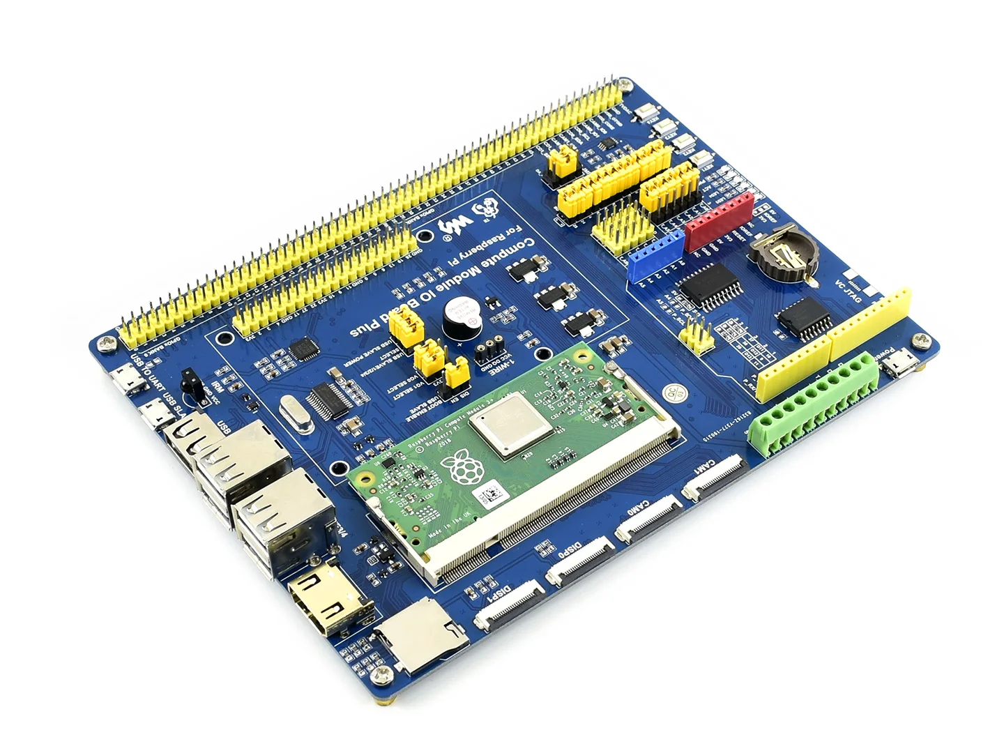
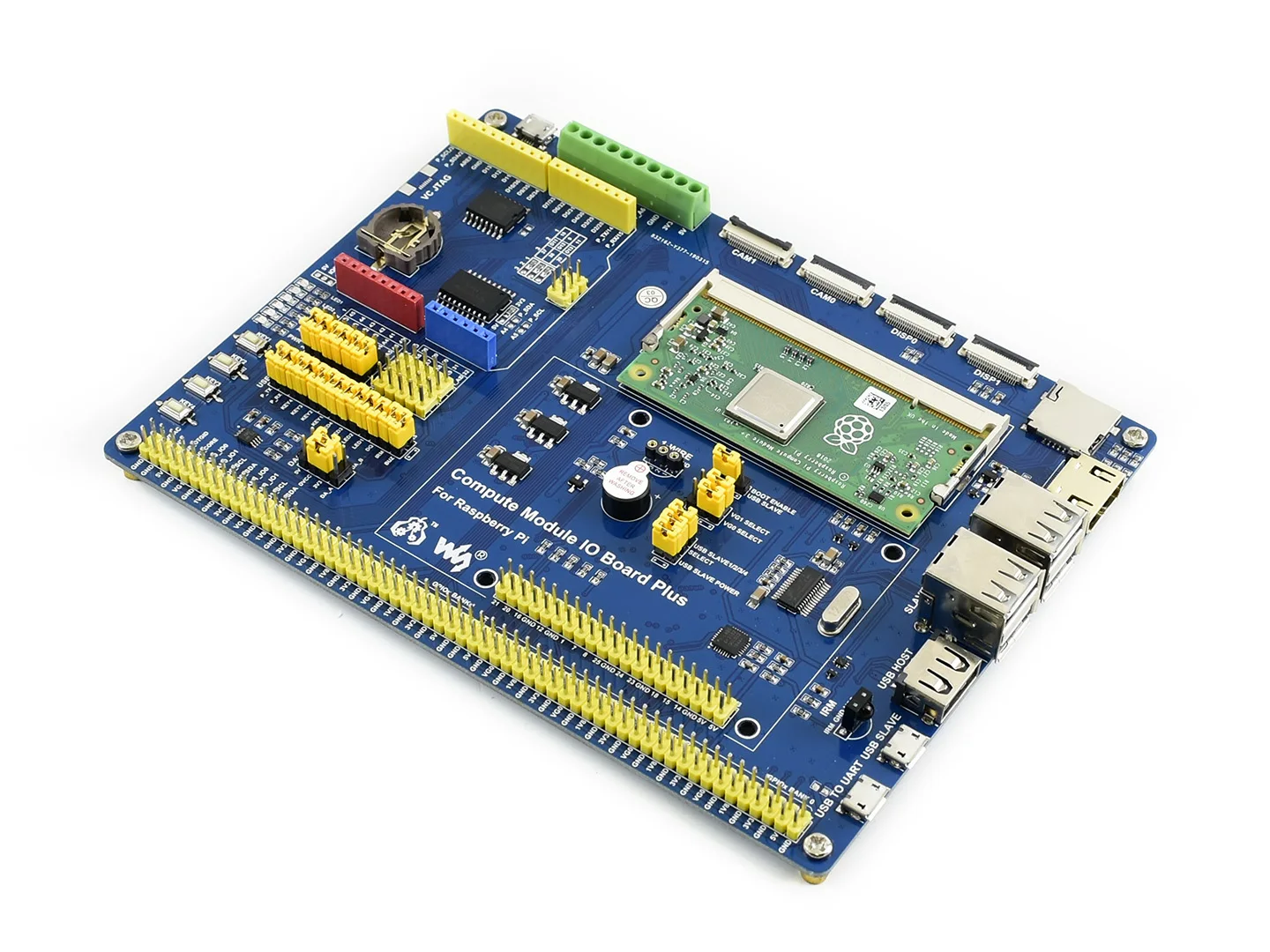
- Compute Module 3+ (optional): Raspberry Pi 3 Model B+ industrial version, the Pi in a flexible form factor, with multi eMMC options, you can also choose to buy the kit without a compute module
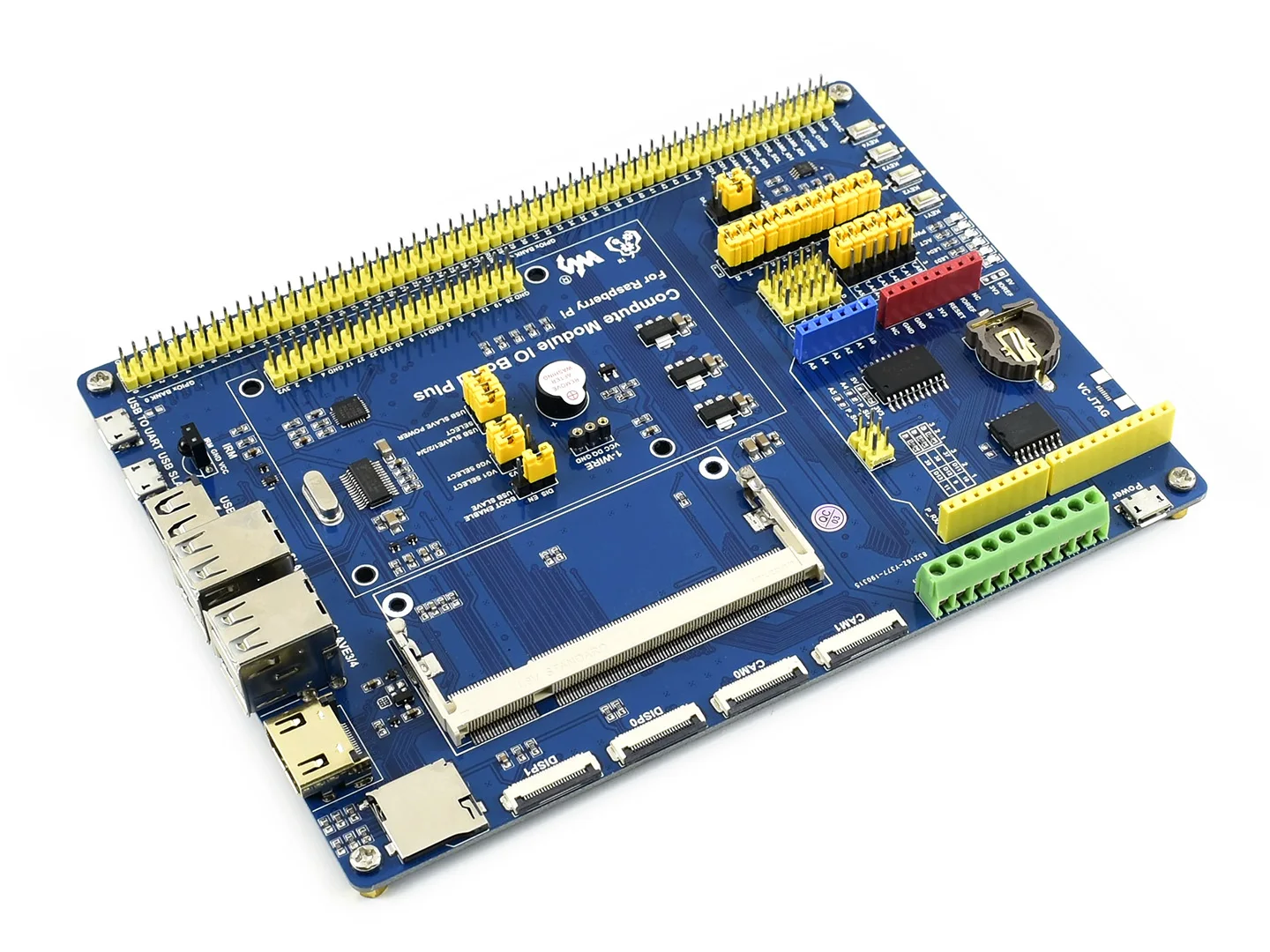
- Compute Module IO Board Plus: Extend kinds of interfaces from CM3+, such as USB, HDMI, just like the regular Pi, to help evaluating
CM3+ Features
- Broadcom BCM2837B0
- Cortex-A53 (ARMv8) 64-bit SoC @ 1.2GHz
- 1GB RAM
- eMMC Flash
- CM3+/Lite: None, but brings the SD card interface to the Module pins so a user can wire this up to an eMMC or SD card
- CM3+/8GB: 8GB
- CM3+/16GB: 16GB
- CM3+/32GB: 32GB
- 200PIN SODIMM connector (35U hard gold plating I/O pins)
- 48 x GPIO
- 2 x I2C
- 2 x SPI
- 2 x UART
- 2 x SD/SDIO (1x SD has been used for eMMC Flash on non-Lite variants)
- 1 x HDMI 1.3a
- 1 x USB2 HOST/OTG
- 1 x DPI (parallel RGB display)
- 1 x NAND(SMI)
- 1 x 4-lane CSI Camera Interface (up to 1Gbps per lane)
- 1 x 2-lane CSI Camera Interface (up to 1Gbps per lane)
- 1 x 4-lane DSI Display Interface (up to 1Gbps per lane)
- 1 x 2-lane DSI Display Interface (up to 1Gbps per lane)
- Compared to CM1, the CM3+ supports more OS, like Windows 10 (the free IOT-specific version from Microsoft)
Compute Module IO Board Plus Features
- Compatible with the Compute Module IO Board V3 from the Raspberry Pi Foundation
- Raspberry Pi GPIO header, for connecting sorts of Raspberry Pi HATs
- connectivity, also supports shields
- 1-WIRE interface, for connecting single-bus devices like DS18B20
- 4x keys, 4x LEDs, 1x Buzzer, for I/O testing
- Onboard USB HUB, allows connecting more USB devices
- IR receiver, IR remote control is available
- Onboard USB TO UART, for serial debugging
- Sensor interface
- 10-bit ADC, 38KSPS, 11-ch (6-ch for interface, 5-ch for sensors)
- 16-bit DAC, 2-ch
- Onboard RTC, one of the most common and useful functions
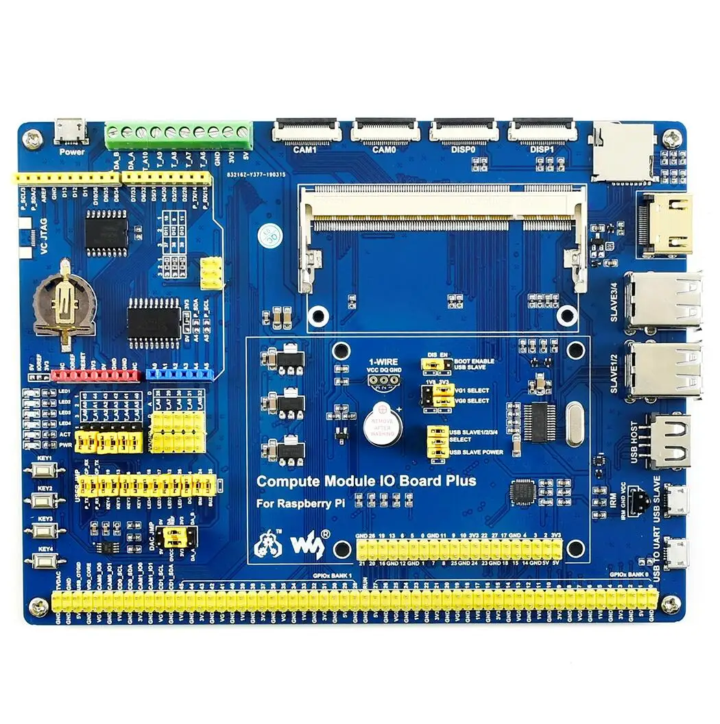
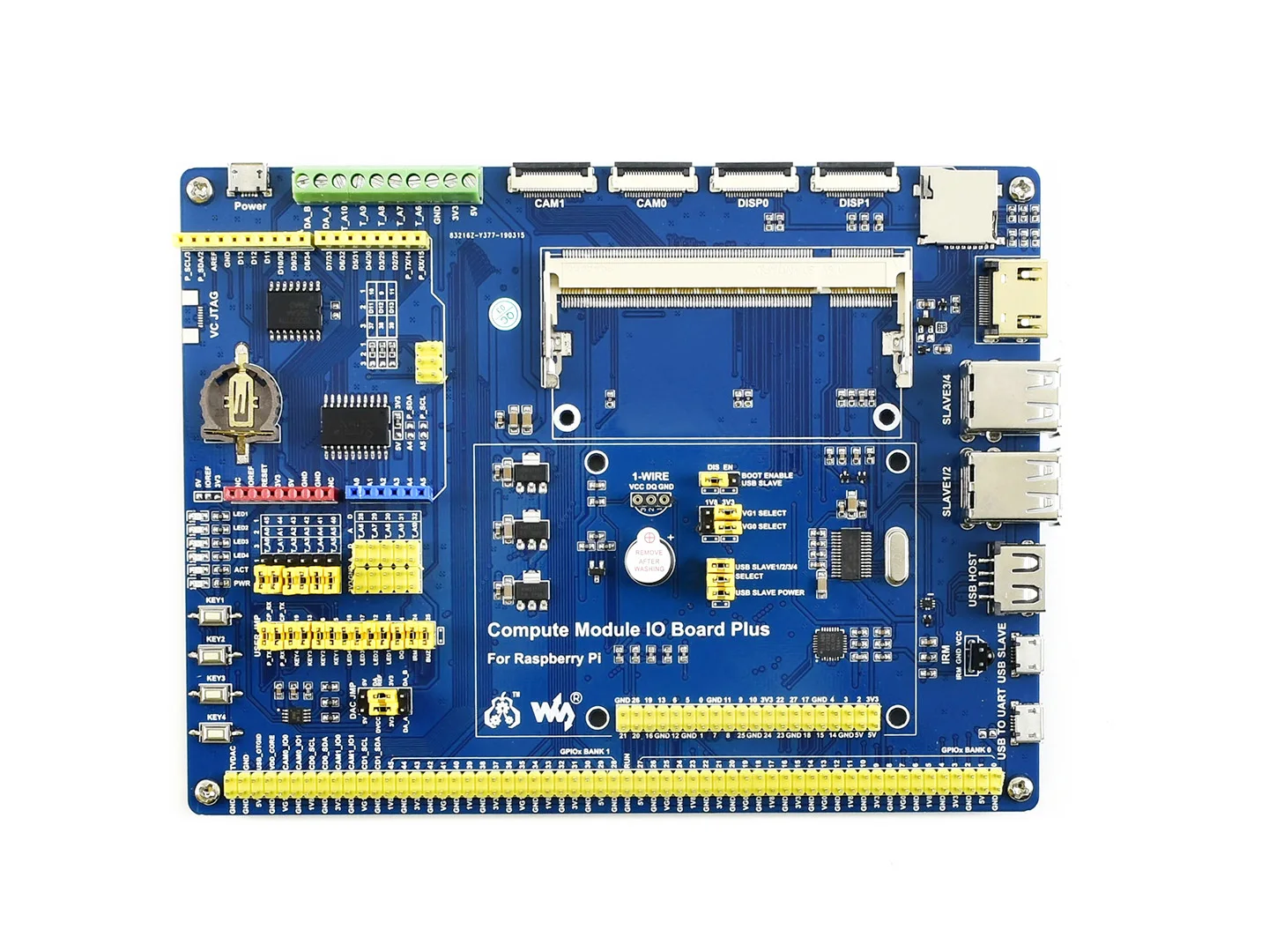
What's on the Compute Module IO Board Plus
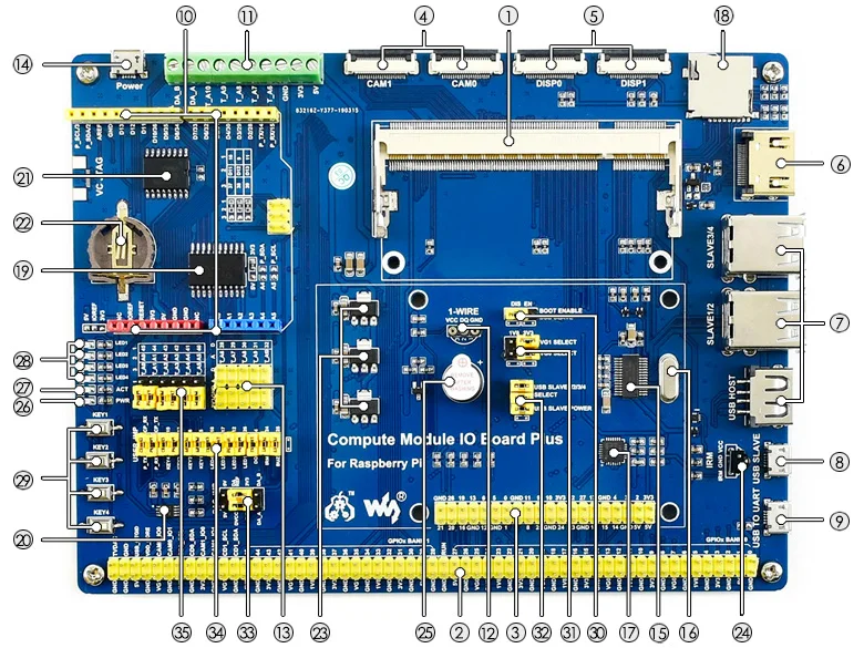
- Compute Module interface: for connecting Compute Module (CM3 / CM3L / CM3+ / CM3+L)
- Compute Module GPIO header: breakout all the Compute Module pins
- Raspberry Pi GPIO header: for connecting Raspberry Pi HATs
- CSI interface: camera ports, for connecting Raspberry Pi Camera
- DSI interface: display ports, for connecting Raspberry Pi LCD
- HDMI port
- USB ports: for connecting USB devices
- USB SLAVE interface: allows you to burn system image in to Compute Module 3/3+
- USB TO UART interface: for serial debugging
- header: for connecting shields
- AD/DA input/output screw terminals
- 1-WIRE interface: for connecting single-bus devices like DS18B20
- Sensor interface
- Power port: 5V 2.5A
- FE1.1S: USB HUB chip
- 12MHz crystal
- CP2102: USB TO UART converter
- Micro SD card slot: insert a Micro SD card with pre-burnt system, to start up Compute Module 3/3+ Lite variant
- TLC1543: AD converter
- DAC8552: 16-bit DAC, 2-ch
- DS3231: high-precision RTC chip, I2C interface
- RTC battery holder: supports CR1220 batteries
- Voltage regulator: 3.3V / 2.5V / 1.8V
- LFN0038K: IR receiver
- Buzzer
- Power indicator
- ACT indicator: indicating the Micro SD card status
- User LEDs
- User Keys
- BOOT selection
- EN: enable the PC to access SD card/eMMC through USB SLAVE
- DIS: the Compute Module will boot from SD card/eMMC
- VGx power selection: config the I/O level
- USB HUB enable jumper: HUB enable and USB SLAVE power selection
- ADC/DAC configuration: config the power supply and reference voltage of ADC/DAC
- Peripheral configuration: config the control pins of UART, user keys, user LEDs, 1-WIRE interface, IR receiver, and buzzer
- AD selection
- connect 1 and 2: A0-A5 as digital control pin
- connect 2 and 3: A0-A5 as AD input


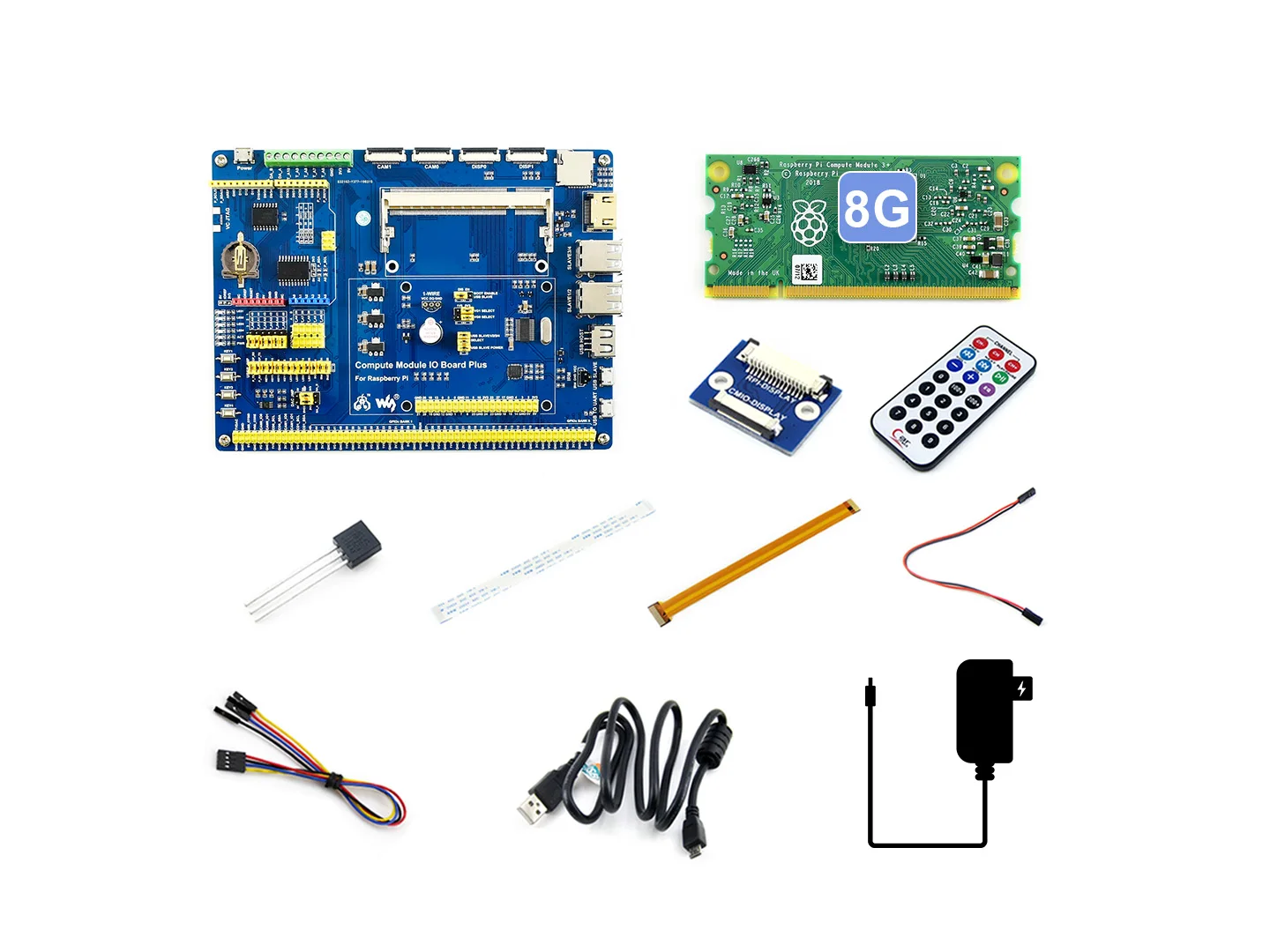
Package Content
- OPTIONS Compute Module 3+ x1
- Compute Module IO Board Plus x1
- DS18B20 x1
- IR remote controller x1
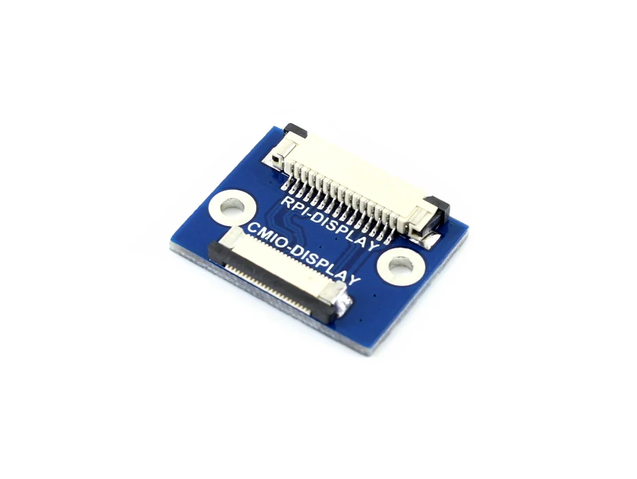
- LCD adapter x1
- 22PIN FFC x1
- RPi Zero V1.3 Camera Cable 15cm x1
- OPTIONS Power adapter 5V/3A micro x1 (EU/US power plug optional)
- USB type A plug to micro B plug cable 120cm x2
- Jumper Wire 4-pin to separated pins x2
- Jumper Wire 2-pin 2.54-pitch 200mm x2

We Recommend


New Arrivals
New products from manufacturers at wholesale prices


