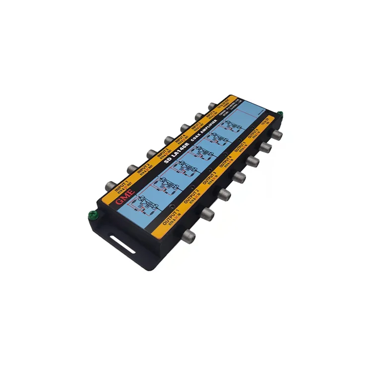
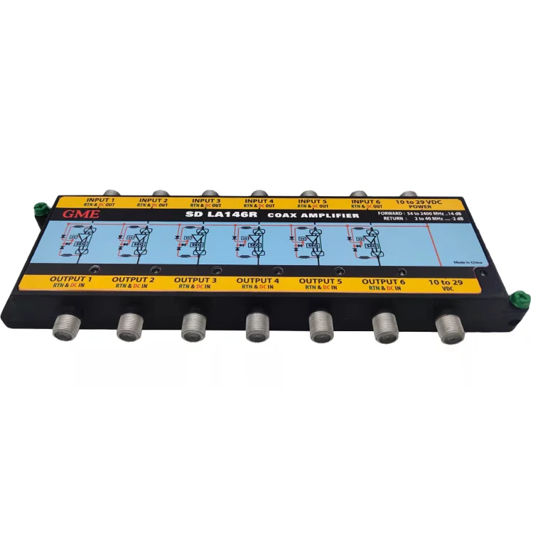
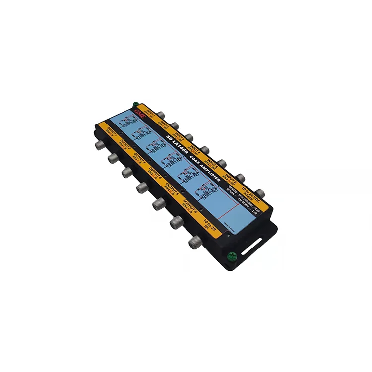
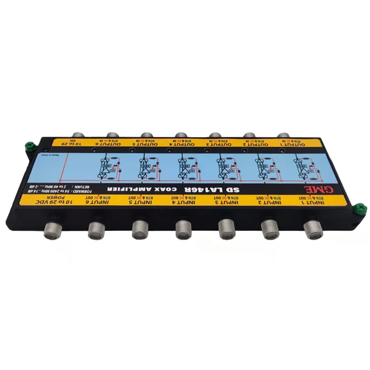
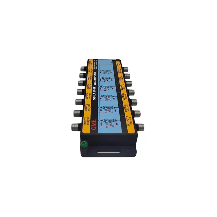
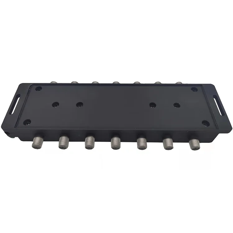
High Density 6 Input Indoor / Outdoor 54 2400 MHz 14dB DBS / ATSC Satellite Line Powered Coax Amplifier
- Category: >>>
- Supplier: Good Mind Electronics (Shenzhen) Co. Ltd.
Share on (1600530100359):
Product Overview
Description

Product Description
Specification
Place of Origin:Guangdong,China | ||||||||||
Model Number:GDAMP-038-2 (LA146R) | ||||||||||
Item | Min | Typ | Max | Unit | Condition | |||||
Number of inputs | 6 | SAT 1 Through SAT 6 | ||||||||
Number of outputs | 6 | OUT 1 Through OUT 6 | ||||||||
Input Frequency Range | 250 | 2150 | MHz | |||||||
Gain at 2150 | 13 | 15 | dB | |||||||
Slope 250 to 2150 MHz | 3 | 4 | 5 | dB | ||||||
Nominal Impedance | 75 | Ω | ||||||||
Return loss (Input and output) | -10 | dB | 250 – 2150 MHz | |||||||
Isolation | 30 | dB | With signal applied to any input and the output as the reference; the isolation measured on all other outputs will be greater than 30 dBc from 250 to 2150 MHz. | |||||||
POWER | ||||||||||
Power supplies | Two 20 Volt 1 A supplies | |||||||||
Voltage applied to the output connectors | 10 | 28 | Vdc | Each individual amplifier will operate per specification when voltage is applied to each amplifiers output connector and will be present at the input connector minus a diode drop | ||||||
Voltage into the input connectors | 10 | 28 | Vdc | Each individual amplifier will operate per specification when voltage is applied to the input connector. Voltage will not appear at the output connector. | ||||||
20 Volts applied to DC LNB port | 20 | This voltage will power all six amplifiers and the 20 volts will be present at the input connector of each amplifier. No voltage will be present at the output connector. | ||||||||
20 Volts applied to DC AMP port | This voltage will power all six amplifiers. No voltage will be present on the input or the output of the amplifiers | |||||||||
20 Volt applied to DC LNB port | 20 | Vdc | 20 Volts applied to the DCLNB port will pass thru to the DC port | |||||||
DC AMP port to DC port current | 1.5 | A | ||||||||
Peak Applied Voltage | 28 | Vdc | Must survive when applied to any or all ports for ≤ 24 hours. | |||||||
DC Current Pass Range | 0 | 1.5 | A | |||||||
DC Resistance | 0.2 | Ohms | Does not apply to cable | |||||||
DC Voltage Drop | 0.4 | Vdc | Does not apply to cable | |||||||
DiSEq | ||||||||||
DiSEqC Frequency Range | 17.6 | 22 | 26.4 | kHz | Must pass with no degradation or distortions. | |||||
Reference the Eutelsat DiSEqC 2.0 Spec. | ||||||||||
DiSEqC Device Impedance | 1000 | Ω | The impedance the device presents with respect to ground. Across the DiSEqC Frequency Range | |||||||
DiSEqC Through Impedance | 1 | Ω | The impedance the device has in the pass through path. Across the DiSEqC Frequency Range. | |||||||
ETC Control Words for 13/18 Switching | Must pass with no degradation or distortions. Their presence must not affect RF performance. | |||||||||
Reference the EchoStar 13/18 Switch Box Function Spec. | ||||||||||
Company Profile

Why Choose Us

Factory Strength

Our Advantages


Packaging&Transport

FAQ

We Recommend
New Arrivals
New products from manufacturers at wholesale prices