
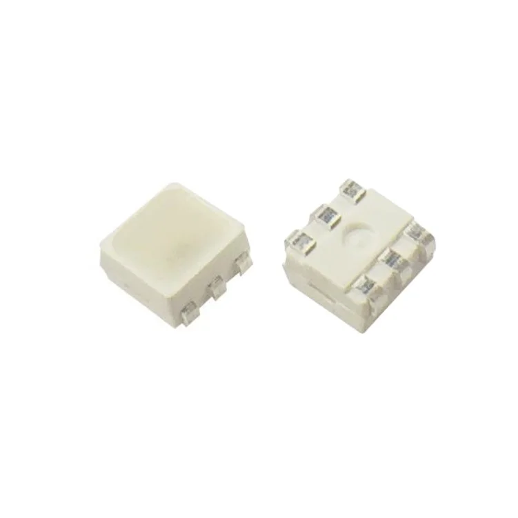
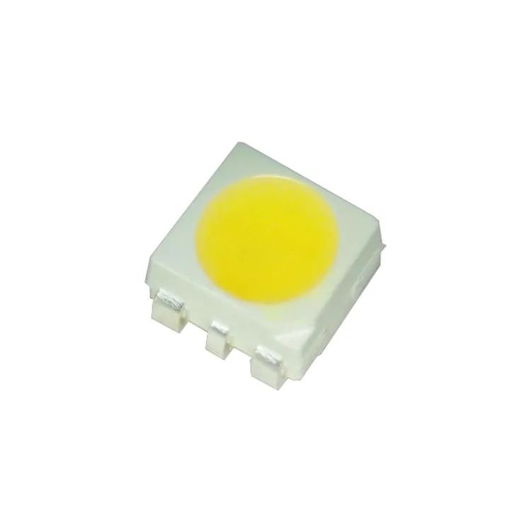
Cheap And High Quality 0.5w Diode Red Led Professional Factory 3433 SMD LED For Turn Signal Light
- Category: >>>
- Supplier: Shenzhen Hongying Technology Co. Ltd.
Share on (1600534909348):
Product Overview
Description
Products Description
Applications
1, Ambient light
2, Lnterior Automotive Lighting
3, RGB displays
4, Electronic Equipment
Maximum Rating (Ta=25℃)
Parameter | Symbol | Value | Unit | |||
DC forward current | IF | 50 | mA | |||
Pulse forward current | IPF*3 | 100 | mA | |||
Reverse voltage | VR | 5 | V | |||
Junction temperature | TJ | 110 | ℃ | |||
Operating temperature range | TOP | -40~105 | ℃ | |||
Storage temperature range | TSTG | -40~105 | ℃ | |||
Soldering temperature | TSD*2 | 260 | ℃ | |||
Thermal resistance | RthJ-S | 150 | ℃/W | |||
Notes: 1, There is no maximun or typical voltage parameter. 2, For other ambient, limited setting of current will be depended on de-rating curves. 3, Duty 1/10, pulse width 0.1ms. 4, The maximum of soldering time is 5 seconds in TSD | ||||||
Typical Product Characteristics (Ta=25℃)
Parameter | Symbol | Min. | Typ. | Max. | Unit | Test Condition | ||||||||
Forward Voltage | VF | Red | 1.8 | - | 2.6 | V | R= 20mA | |||||||
Green | 2.6 | - | 3.4 | G= 14mA | ||||||||||
Blue | 2.4 | - | 3.2 | B= 6mA | ||||||||||
Luminous Intensity | IV | Red | 425 | 640 | - | mcd | R= 20mA | |||||||
Green | 1450 | 1850 | - | G= 14mA | ||||||||||
Blue | 50 | 70 | - | B= 6mA | ||||||||||
Dominant Wavelength | λd | Red | 625 | - | 635 | nm | R= 20mA | |||||||
Green | 520 | - | 530 | G= 14mA | ||||||||||
Blue | 445 | - | 455 | B= 6mA | ||||||||||
Reverse Current | IR | - | - | 10 | uA | VR=5V | ||||||||
View Angle | 2θ1/2 | - | 120 | - | Deg | R= 20mA, G=14mA, B=6mA | ||||||||
Notes: 1, Tolerance: Forward Voltage: ±0.1V, Luminous Intensity: ±10%Iv, Dominant Wavelength: ±1.0nm 2, Electrical-optical characteristics (Ta= 25℃). 3, We will amend the Bin code to maintain Bin Code centralize. 4, And we get the Luminous Intensity is 1.3double per Bins and the Dominant Wavelength is 5/5/5nm of R/G/B per Bins and white balance. | ||||||||||||||
Dimensional Drawing

Notes:
1, All dimensions are in millimeters.
2, Tolerance is ±0.1mm unless otherwise noted.
3, Specifications are subject to change without notice.


Our Advantages


FAQ

Q:How about the quality of the leds?
A:Please do not worry about the quality. Our company is the main manufacturer of LEDs in China. Our products have exported worldwide since the year 2010.
Q:Do you offer Custom-made ?
A:Yes , we offer this , but we will charge cost for the custom-made samples .
Q:Can I get free sample?
A:Yes, we can offer free sample for you to check before orderas long as you afford the express freight.
Q:What’s the lead time?
A:Samples delivery out in 3-7 working days.Lead time of mass production needs to negotiate, it depends on quantity.
Q:How about the payment terms?
A:Payment terms: TT in advance (30% of deposit before production and 70% balance before shipment). Please note we do EXW/FOB/CNF/CIF/DDU/DDP.

We Recommend


New Arrivals
New products from manufacturers at wholesale prices


