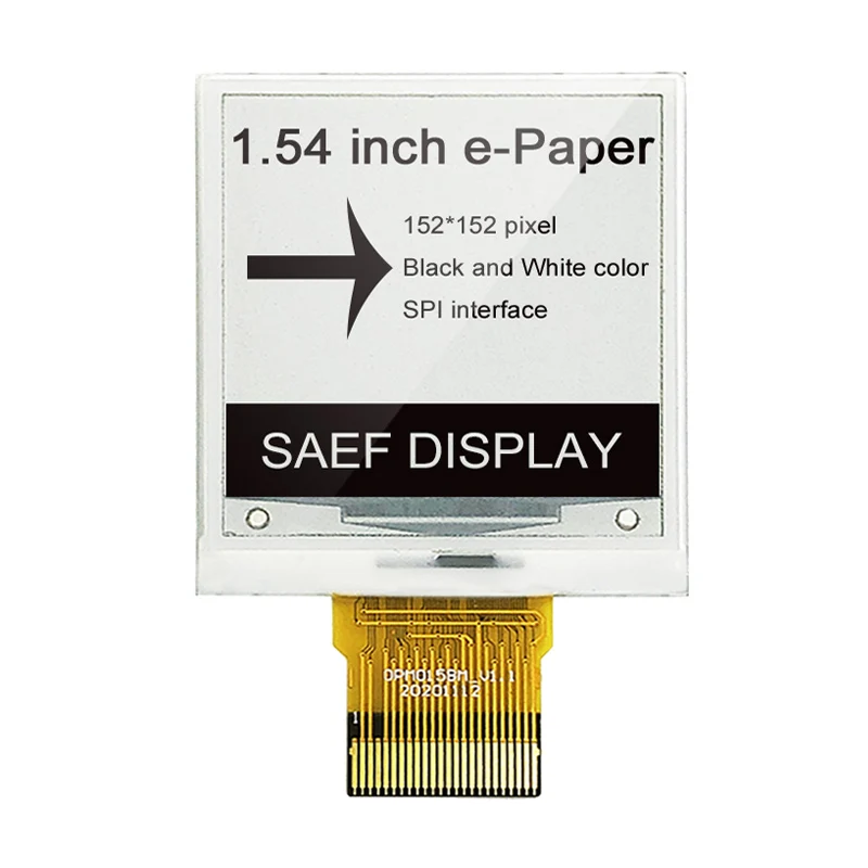
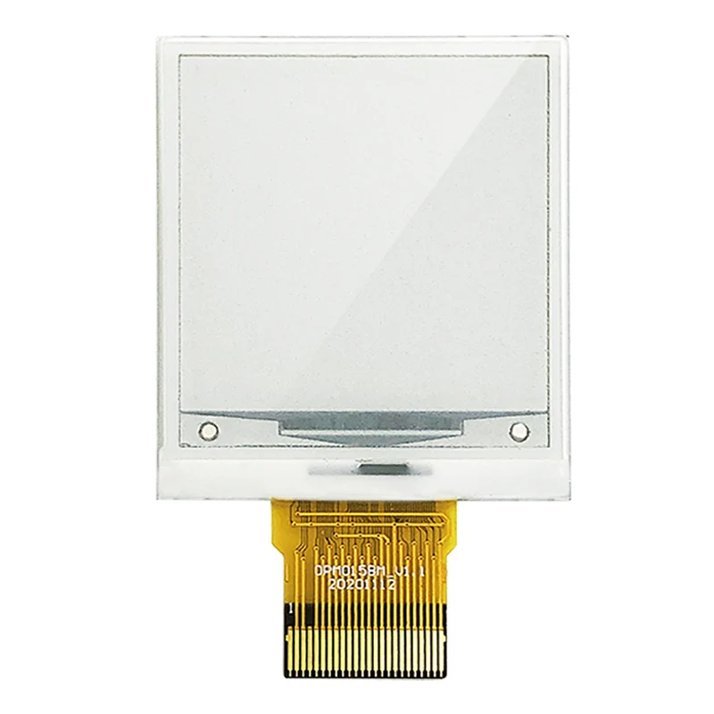
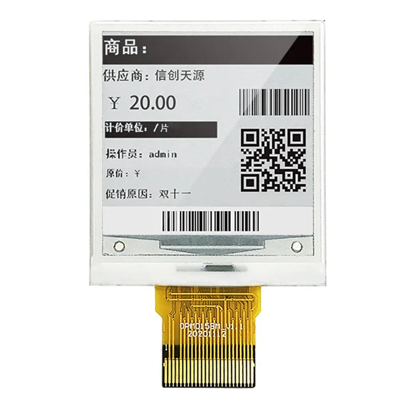
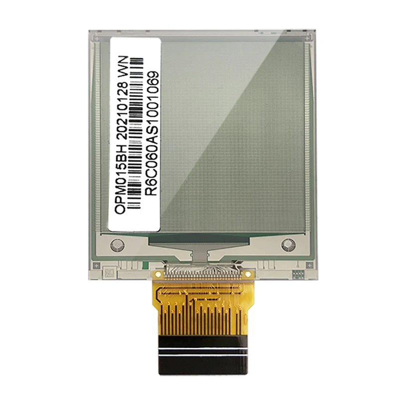
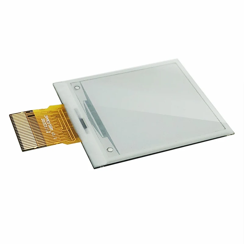
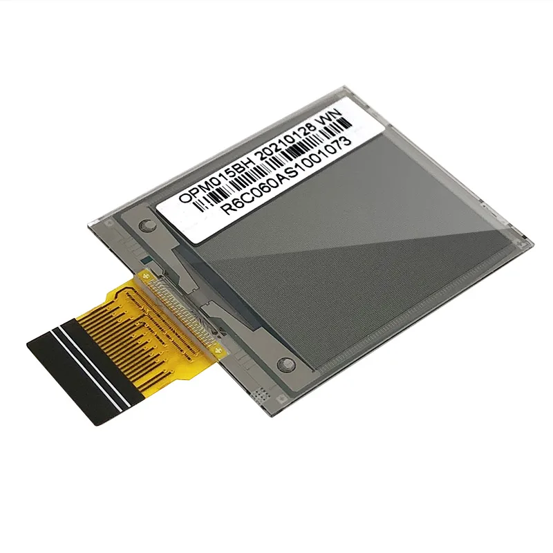
1.54 Inch E Ink Display 152x152 Dots MCU Interface EPD Panel oled/e paper module e ink display
- Category: >>>
- Supplier: Shenzhen Saef Technology Ltd.
Share on (1600567085026):
Product Overview
Description
Product Description
Item of general information | Contents |
Screen Size | 1.54 inch EPD Panel |
Display Mode | Active Matrix EPD |
Display Resolution | 152(H)×152(V) Pixels |
Active Area | 27.512 (H) × 27.512 (V) mm |
Pixel Pitch | 0.181(H) × 0.181(V) |
PixelConfiguration | Rectangle |
Outline Dimension | 31.80 (H) × 37.32(V ×1.14(D) mm |
Weight | 2.7 g |
Logic supply voltage | 3.0V typical |
Operation Temperature | 0°C to +35°C |
Storage Temperature | -25°C to +60°C |
Interface | MCU |
Compliance | REACH & RoHS Compliant |

Product performance description
Found in 2007, SAEF TECH is an experienced LCD/LCM manufacturer. With good quality, professional service and competitive price, we
have been qualified by many well-known companies around the world. SAEF's main advantages that distinguish us from other LCD
vendors are as below: (1) Professional team that have accumulated rich experiences in design/mfg/quality control. (2) Flexible in
biz to support both big and small qty projects from customers. (3) Long product lifetime and Constant Quality product.
have been qualified by many well-known companies around the world. SAEF's main advantages that distinguish us from other LCD
vendors are as below: (1) Professional team that have accumulated rich experiences in design/mfg/quality control. (2) Flexible in
biz to support both big and small qty projects from customers. (3) Long product lifetime and Constant Quality product.
E-ink Display 1.54 inch, EPD 1.54 inch Screen Description
SAEF Technology SFEPD154H-7003A01 is an Active Matrix Electrophoretic Display(AM EPD), with interface and a reference system design. The 1.54” active area contains 152x152 pixels, and has 2-bit full display capabilities. The module is a TFT-array driving electrophoretic display, with integrated circuits including gate buffer, source buffer, MCU interface, timing control logic,oscillator, DC-DC, SRAM, LUT, VCOM. Module can be used in portable electronic devices, such as Electronic Shelf Label (ESL) System.
Features
◆ 152×152pixels display
◆ White reflectance above 30%
◆ Contrast ratio above 10:1
◆ Ultra wide viewing angle
◆ Ultra low power consumption
◆ Pure reflective mode
◆ Bi-stable display
◆ Ultra Low current deep sleep mode
◆ On chip display RAM
◆ Waveform stored in On-chip OTP
◆ Serial peripheral interface available
◆ On-chip oscillator
◆ On-chip booster and regulator control for generating VCOM, Gate and Source driving voltage
◆ I 2C signal master interface to read external temperature sensor
Features
◆ 152×152pixels display
◆ White reflectance above 30%
◆ Contrast ratio above 10:1
◆ Ultra wide viewing angle
◆ Ultra low power consumption
◆ Pure reflective mode
◆ Bi-stable display
◆ Ultra Low current deep sleep mode
◆ On chip display RAM
◆ Waveform stored in On-chip OTP
◆ Serial peripheral interface available
◆ On-chip oscillator
◆ On-chip booster and regulator control for generating VCOM, Gate and Source driving voltage
◆ I 2C signal master interface to read external temperature sensor
Application
Electronic Shelf Label System
Pin Definition
Pin1, NC Do not connect with other NC pins
Pin2, GDR / O / N-Channel MOSFET Gate Drive Control
Pin3, RESE / I / Current Sense Input for the Control Loop
Pin4, NC Do not connect with other NC pins
Pin5, VDHR / C / Positive Source driving voltage 1
Pin6, TSCL / O / I2C Interface to digital temperature sensor Clock pin
Pin7, TSDA / I/O / I2C Interface to digital temperature sensor Data pin
Pin8, BS / I / Bus Interface selection pin
Pin9, BUSYN / O / Busy state output pin
Pin10, RSTN / I / Reset signal input. Active Low.
Pin11, D/C / I / Data /Command control pin
Pin12, CSB / I / Chip select input pin
Pin13, SCL / I / Serial Clock pin (SPI)
Pin14, SDA / I / Serial Data pin (SPI)
Pin15, VDD / P / Power Supply for interface logic pins
Pin16, VDD / P / Power Supply for the chip
Pin17, VSS / P / Ground
Pin18, VDDD / C / Core logic power pin VDDD can be regulated internally from VDD. A capacitorshould be connected between VDDD and
VSS under all circumstances
Pin19, VPP / P / Power Supply for OTP Programming
Pin20, VSH / C / Positive Source driving voltage 2
Pin21, VGH / C / Positive Gate driving voltage
Pin22, VSL / C / Negative Source driving voltage
Pin23, VGL / C / Negative Gate driving voltage
Pin24, VCOM / C / VCOM driving voltage
I = Input Pin, O =Output Pin, I/O = Bi-directional Pin (Input/Output), P = Power Pin, C = Capacitor Pin
Pin Definition
Pin1, NC Do not connect with other NC pins
Pin2, GDR / O / N-Channel MOSFET Gate Drive Control
Pin3, RESE / I / Current Sense Input for the Control Loop
Pin4, NC Do not connect with other NC pins
Pin5, VDHR / C / Positive Source driving voltage 1
Pin6, TSCL / O / I2C Interface to digital temperature sensor Clock pin
Pin7, TSDA / I/O / I2C Interface to digital temperature sensor Data pin
Pin8, BS / I / Bus Interface selection pin
Pin9, BUSYN / O / Busy state output pin
Pin10, RSTN / I / Reset signal input. Active Low.
Pin11, D/C / I / Data /Command control pin
Pin12, CSB / I / Chip select input pin
Pin13, SCL / I / Serial Clock pin (SPI)
Pin14, SDA / I / Serial Data pin (SPI)
Pin15, VDD / P / Power Supply for interface logic pins
Pin16, VDD / P / Power Supply for the chip
Pin17, VSS / P / Ground
Pin18, VDDD / C / Core logic power pin VDDD can be regulated internally from VDD. A capacitorshould be connected between VDDD and
VSS under all circumstances
Pin19, VPP / P / Power Supply for OTP Programming
Pin20, VSH / C / Positive Source driving voltage 2
Pin21, VGH / C / Positive Gate driving voltage
Pin22, VSL / C / Negative Source driving voltage
Pin23, VGL / C / Negative Gate driving voltage
Pin24, VCOM / C / VCOM driving voltage
I = Input Pin, O =Output Pin, I/O = Bi-directional Pin (Input/Output), P = Power Pin, C = Capacitor Pin
Related Products


We Recommend

New Arrivals
New products from manufacturers at wholesale prices