

OpenH743I C Standard STM32H7 Development Board
- Category: >>>
- Supplier: Guangzhou Zhongchuang Youpin Technology Co. Ltd.
Share on (1600568724177):
Product Overview
Description
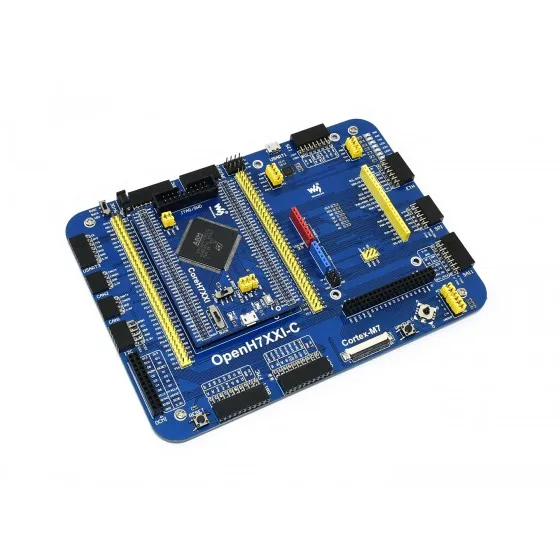
OpenH743I-C is an STM32 development board designed for the STM32H743IIT6 microcontroller, consists of the mother board and the MCU core board CoreH743I.
The OpenH743I-C supports further expansion with various optional accessory boards for specific application. The modular and open design makes it the ideal for starting application development with STM32 series microcontrollers.
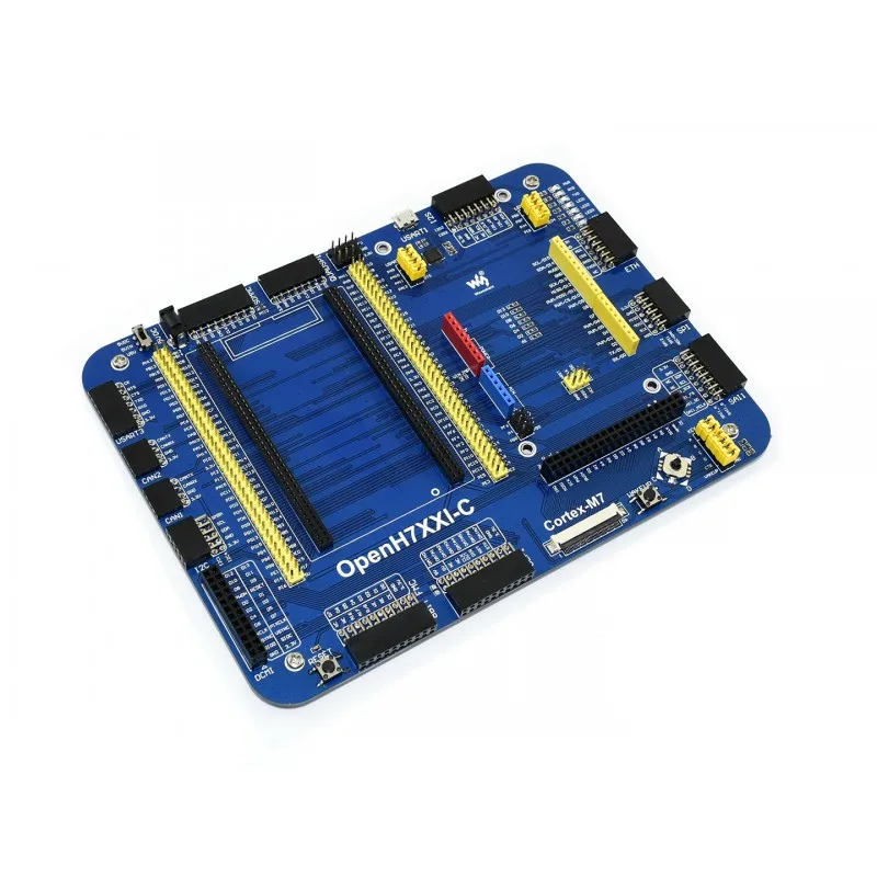
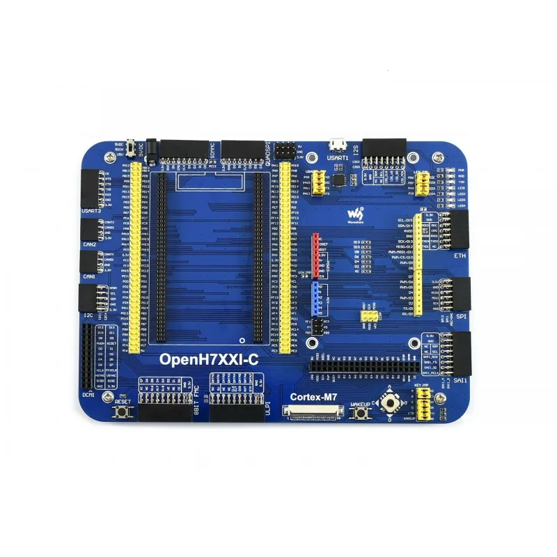
What's on the mother board

- MCU core board connector: for easily connecting the CoreH743I
- Arduino interface: for connecting Arduino shields
- DCMI interface: for connecting camera
- 8-bit FMC interface: easily connects to peripherals such as NandFlash
- ULPI interface: for connecting high-speed USB peripheral (the STM32H743I integrates USB HS controller without any PHY device)
- LCD interface 1: for connecting 10.1inch LCD, 7inch LCD, 4.3inch LCD
- LCD interface 2: for connecting 4.3inch LCD
- SAI1 interface: for connecting audio modules
- ICSP interface: Arduino ICSP
- SPI interfaces:
- easily connects to SPI peripherals such as DataFlash (AT45DBxx, W25QXX), SD card, MP3 module, etc.
- easily connects to AD/DA modules (SPI1 features AD/DA alternative function)
- Ethernet interface: for connecting Ethernet modules
- I2S / I2C interface: easily connects to I2S peripherals such as audio module, etc.
- USART1 connector: USB to UASRT via the onboard convertor CP2102
- QUADSPI interface: 4-wires SPI interface (the H7 series latest peripheral interface), for connecting serial Flash modules like W25QXX Board
- SDMMC interface: for connecting Micro SD module, features much faster access speed rather than SPI
- USART3 interface: easily connects to RS232, RS485, USB TO 232, etc.
- CAN2 interface: for connecting CAN modules
- CAN1 interface: for connecting CAN modules
- I2C1/I2C4 interface: easily connects to I2C peripherals such as I/O expander (PCF8574), EEPROM (AT24Cxx), 10 DOF IMU Sensor, etc.
- MCU pins connector: all the MCU I/O ports are accessible on expansion connectors for further expansion
- 5V DC jack
- 5V/3.3V power input/output: usually used as power output, also common-grounding with other user board
- Power supply switch: powered from 5VDC OR USB connection of the USART1
- CP2102: USB to UART convertor
- LEDs: convenient for indicating I/O status and/or program running state
- Joystick: five positions
- WAKE UP button: used as regular button, and/or wake up the STM32 MCU from sleep
- Reset button
- USART1 jumper
- LED jumper
- short the jumper to connect to default I/Os used in example code
- open the jumper to connect to custom I/Os via jumper wires
- KEY jumper
- short the jumper to connect to default I/Os used in example code
- open the jumper to connect to custom I/Os via jumper wires
- Arduino jumper
- short the upper pins, A4, A5 is used as AD function
- short the lower pins, A4, A5 is used as I2C function
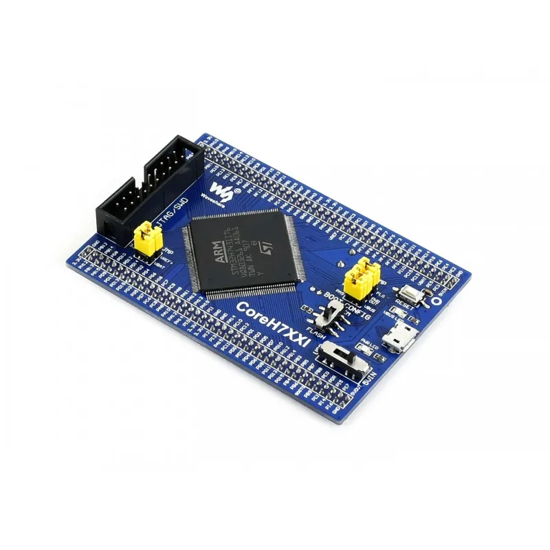
What's on the CoreH743I

- STM32H743IIT6:the high performance STM32 MCU which features:
- Core: Cortex-M7 32-bit RISC + double-precision FPU + Chrom-ART graphic accelerator
- Feature: single-cycle DSP instructions
- Operating Frequency: 480MHz, 1027 DMIPS / 2.14 DMIPS/MHz
- Operating Voltage: 1.62V-3.6V
- Package: LQFP176
- Memories: 2MB Flash, 1MB RAM (864KB User+192KB TCM+4KB Backup)
- MCU communication Interfaces:
- 6 x SPI, 4 x USART, 4 x UART, 1 x LPUART, 3 x I2S
- 4 x I2C, 2 x FDCAN, 1 x QUAD-SPI, 1 x DCMI, 4 x SAI
- 1 x FMC, 2 x SDMMC, 10 x TIM , 5 x LPTIM
- 1 x LTDC, 1 x SPDIFRX, 1 x HDMI-CEC, 1 x SWPMI
- 2 x COMP, 2 x OPAMP, 1 x HRTIM, 1 x RNG, 1 x DM2D, 1 x MDIO, 1 x SysTick
- 1 x USB 2.0 OTG FS
- 1 x USB 2.0 OTG HS (supports external HS PHY through ULPI)
- 1 x 10/100 Ethernet MAC
- AD & DA converters: 3 x AD (16-bit); 2 x DA (12-bit)
- Debugging/Programming: supports JTAG/SWD interfaces, supports IAP
- IC42S16400J / IS42S16400J: SDRAM 1 Meg Bits x 16 Bits x 4 Banks (64-MBIT)
- STMPS2151STR: onboard USB power management device
- AMS1117-3.3: 3.3V voltage regulator
- 8M crystal
- 32.768K crystal, for internal RTC with calibration
- Reset button
- VBUS LED: USB port indicator
- PWR LED: Power indicator
- Power supply switch, powered from 5Vin or USB connection
- Boot mode selection, for configuring BOOT0 pin
- JTAG/SWD interface: for debugging/programming
- USB connector, supports Device and/or Host
- MCU pins expander, VCC, GND and all the I/O pins are accessible on expansion connectors for further expansion
- POWER jumper
- VBAT: short the jumper to use system power supply, open it to connect external power, such as battery
- VREF: short the jumper to connect VREF+ to VCC, open it to connect VREF+ to other custom pin via jumper wire
- OTG jumper
- short the jumper when using USB OTG/HOST
- open the jumper to disconnect from related I/O port
Note:
The Modules in the photos are for reference only.
The OpenH743I-C does NOT integrate any debugging function, a debugger is required.
JTAG/SWD interfaces
The figure 1, and 2 show the header pinouts of JTAG/SWD interface


Development Resources
- Schematic
- Demo code (examples in C, FreeRTOS, μC/OS-III)
- STM32 development software (KEIL, STM32CubeMX, etc.)
- STM32 datasheets
- STM32 development documentations
Wiki: www.waveshare.com/wiki/OpenH743I-C
Dimensions

We Recommend


New Arrivals
New products from manufacturers at wholesale prices


