
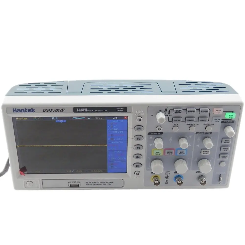
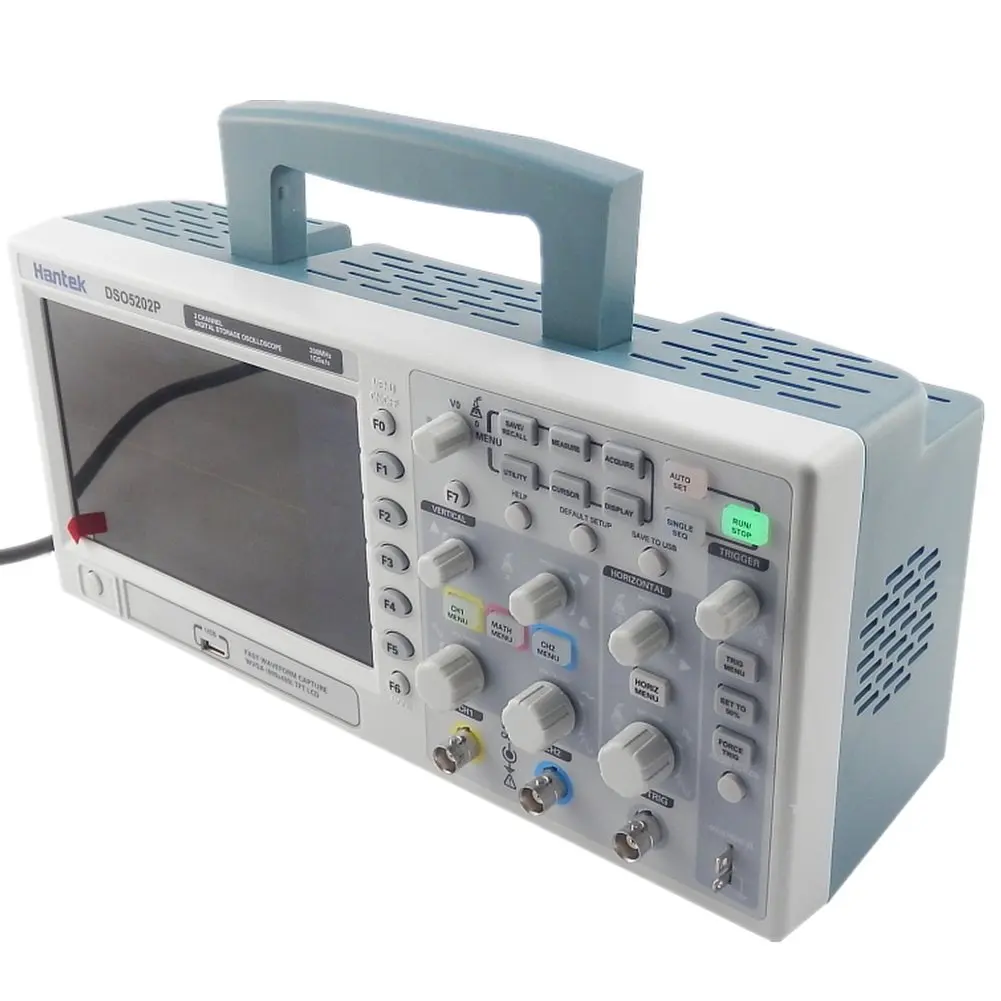
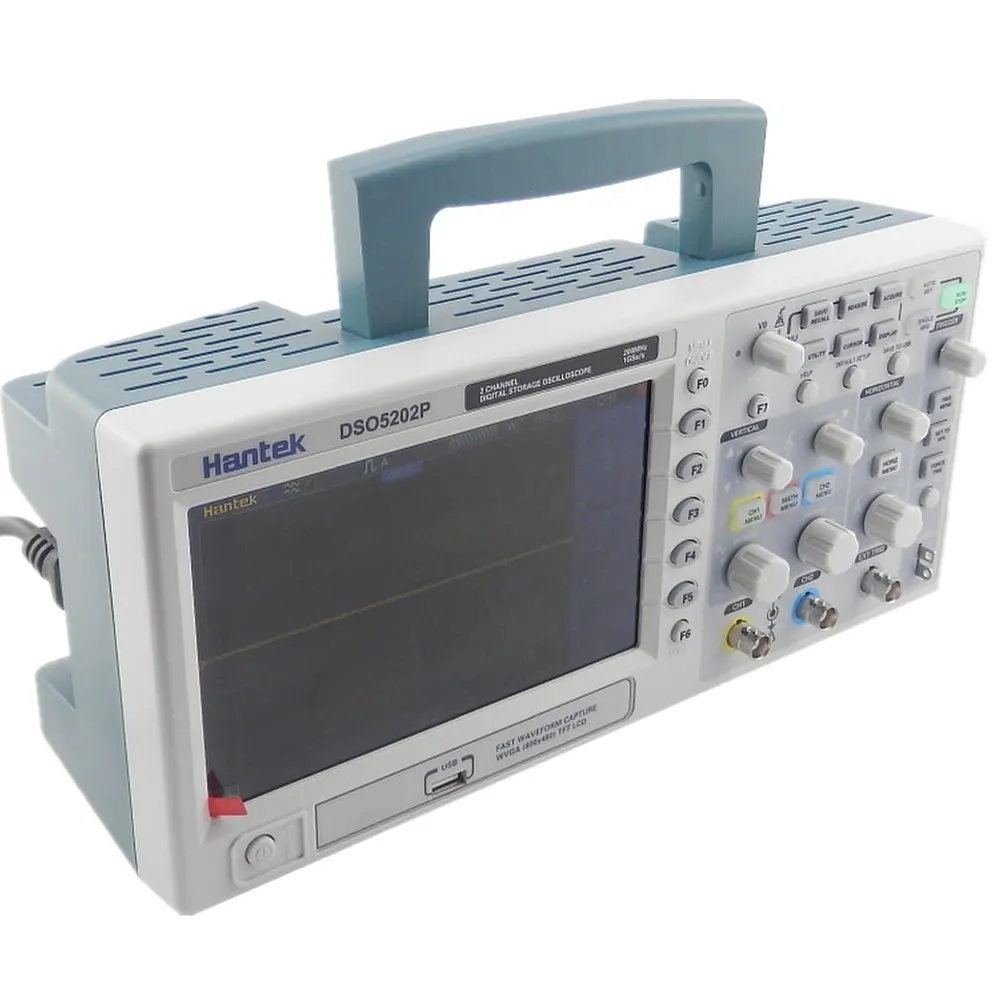
Digital Oscilloscope 200mhz Hantek Dso5202p Bandwidth 2 Channels Pc Usb Lcd Portable Osciloscopio Electrical Tools
- Category: >>>
- Supplier: Shenzhen Robotlinking Technology Co. Ltd.
Share on (1600616769674):
Product Overview
Description

Product Description
Digital Oscilloscope 200mhz Hantek Dso5202p Bandwidth 2 Channels Pc Usb Lcd Portable Osciloscopio Electrical Tools
Feature:
* Large (7.0-inch) color display, WVGA(800x480)
* 100MHz bandwidths with 1GSa/s Real Time sample rate
* Trigger mode: Edge, Pulse Width, Video, Slop,Overtime, Alternative trigger etc
* 32 automatic measurements and track measurement via cursor automatically
* Five math functions, including FFTs standard
* Provides software for PC real-time analysis
* Support U disk and local files storage
* Built in Bode diagram Assistant
Model | DSO5202P | DSO5102P | DSO5072P | |||
Bandwidth | 200MHz | 100MHz | 70MHz | |||
Rise Time at BNC( typical) | <1.8ns | <3.5ns | <5ns | |||
Sample Rate | Real-Time Sample: 1GS/s | |||||
Equivalent Sample: 25GS/s | ||||||
Acquisition Modes | ||||||
Normal | Normal data only | |||||
Peak Detect | High-frequency and randon glith capture | |||||
Average | Wavefom Average, selectable 4,8,16,32,64,128 | |||||
Inputs | ||||||
Inputs Coupling | AC, DC, GND | |||||
Inpits Impendance | 1MΩ±2% ll20pF±3pF | |||||
Probe Attenuation | 1X, 10X | |||||
Supported Probe Attenuation Factor | 1X, 10X, 100X, 1000X | |||||
Maximum Input Voltage | CAT I and CAT II:300VRMS (10×), Installation Category; | |||||
CAT III:150VRMS (1×); | ||||||
Horizontal | ||||||
Sample Rate Range | 500MS/s--1GS/s | |||||
Waveform Interpolation | (sin x)/x | |||||
Record Length | 40K | |||||
SEC/DIV Range | 2ns/div to 40s/div | 4ns/div to 40s/div | ||||
Sample Rate and Delay Time Accuracy | ±50ppm(at over any ≥1ms time interval) | |||||
Position Range | 2ns/div to 10ns/div; | 20ns/div to 80us/div; (-8div x s/div) to 40ms; | ||||
(-4div x s/div) to 20ms; | 200us/div to 40s/div; (-8div x s/div) to 400s | |||||
Delta Time Measurement Accuracy (Full Bandwidth) | Single-shot, Normal mode:± (1 sample interval +100ppm × reading + 0.6ns); >16 averages:± (1 sample interval + 100ppm × reading + 0.4ns); Sample interval = s/div ÷ 200 | |||||
Vertical | ||||||
Vertical Resolution | 8-bit resolution, all channel sampled simultaneously | |||||
Position Range | 2mV/div to 200mV/div, ±2V | |||||
200mV/div to 5V/div, ±50V | ||||||
Analog Bandwidth in Normal and Average modes at BNC or with probe, DC Coupled | 2mV/div to 20mV/div, ±400mV; 50mV/div to 200mV/div, ±2V 500mV/div to 2V/div, ±40V; 5V/div, ±50V | |||||
Math | +, -, *, /, FFT | |||||
FFT | Windows: Hanning, Flatop, Rectamgular, Bartlett, Blackman; | |||||
1024 sample point | ||||||
Bandwidth Limit | 20MHz | |||||
Low Frequency Response (-3db) | ≤10Hz at BNC | |||||
DC Gain Accuracy | ±3% for Normal or Average acquisition mode, 5V/div to 10mV/div; | |||||
±4% for Normal or Average acquisition mode, 5mV/div to 2mV/div | ||||||
Trigger System | ||||||
Trigger Types | Edge, Video, Pulse, Slope, Over time, Alternative | |||||
Trigger Source | CH1, CH2, EXT, EXT/5, AC Line | |||||
Trigger Modes | Auto, Normal, Single | |||||
Coupling Type | DC, AC, Noise Reject, HF Reject, LF Reject | |||||
Trigger Sensitivity (Edge Trigger Type) | DC(CH1,CH2):1div from DC to 10MHz; 1.5div from 10MHz to 100MHz; 2div from 100MHz to Full; | |||||
DC(EXT): 200mV from DC to 100MHz; 350mV from 100MHz to 200MHz; | ||||||
DC(EXT/5):1V from DC to 100MHz;1.75V from 100MHz to 200MHz; | ||||||
AC: Attenuates signals below 10Hz; | ||||||
HF Reject: Attenuates signals above 80kHz; | ||||||
LF Reject: Same as the DC-coupled limits for frequencies above 150kHz; attenuates signals below 150kHz | ||||||
Trigger Level Range | CH1/CH2: ±8 divisions from center of screen; | |||||
EXT: ±1.2V; | ||||||
EXT/5:±6V | ||||||
Trigger Level Accuracy( typical)Accuracy is for signals having rise and fall times ≥20ns | CH1/CH2: 0.2div × volts/div within ±4 divisions from center of screen; | |||||
EXT: ± (6% of setting + 40mV); | ||||||
EXT/5: ± (6% of setting + 200mV); | ||||||
Set Level to 50%(typical) | Operates with input signals ≥50Hz | |||||
Video Trigger | ||||||
Video Trigger Type | CH1, CH2: Peak-to-peak amplitude of 2 divisions; | |||||
EXT: 400mV; | ||||||
EXT/5: 2V | ||||||
Signal Formats and Field Rates, Video Trigger Type | Supports NTSC, PAL and SECAM broadcast systems for any field or any line | |||||
Holdoff Range | 100ns ~ 10s | |||||
Pulse Width Trigger | ||||||
Pulse Width Trigger Mode | Trigger when (< , >, = , or ≠); Positive pulse or Negative pulse | |||||
Pulse Width Trigger Point | Equal: The oscilloscope triggers when the trailing edge of the pulse crosses the trigger level. | |||||
Not Equal: If the pulse is narrower than the specified width, the trigger point is the trailing edge. Otherwise, the oscilloscope triggers when a pulse continues longer than the time specified as the Pulse Width. | ||||||
Less than: The trigger point is the trailing edge. | ||||||
Greater than (also called overtime trigger): The oscilloscope triggers when a pulse continues longer than the time specified as the Pulse Width | ||||||
Pulse Width Range | 20ns ~ 10s | |||||
Slope Trigger | ||||||
Slope Trigger Mode | Trigger when (< , > , = , or ≠ ); Positive slope or Negative slope | |||||
Slope Trigger Point | Equal: The oscilloscope triggers when the waveform slope is equal to the set slope. | |||||
Not Equal: The oscilloscope triggers when the waveform slope is not equal to the set slope. | ||||||
Less than: The oscilloscope triggers when the waveform slope is less than the set slope. | ||||||
Greater than: The oscilloscope triggers when the waveform slope is greater than the set slope. | ||||||
Time Range | 20ns ~ 10s | |||||
Overtime Trigger | ||||||
Over Time Mode | Rising edge or Falling edge | |||||
Time Range | 20ns ~ 10s | |||||
Alternative Trigger | ||||||
Trigger on CH1 | Internal Trigger: Edge, Pulse Width, Video, Slope | |||||
Trigger on CH2 | Internal Trigger: Edge, Pulse Width, Video, Slope | |||||
Trigger Frequency Counter | ||||||
Readout Resolution | 6 digits | |||||
Accuracy (typical) | ±30ppm (including all frequency reference errors and ±1 count errors) | |||||
Frequency Range | AC coupled, from 4Hz minimum to rated bandwidth | |||||
Signal Source | Pulse Width or Edge Trigger modes: all available trigger sources | |||||
The Frequency Counter measures trigger source at all times, including when the oscilloscope acquisition pauses due to changes in the run status, or acquisition of a single shot event has completed. | ||||||
Pulse Width Trigger mode: The oscilloscope counts pulses of significant magnitude inside the 1s measurement window that qualify as triggerable events, such as narrow pulses in a PWM pulse train if set to < mode and the width is set to a relatively small time. | ||||||
Edge Trigger mode: The oscilloscope counts all edges of sufficient magnitude and correct polarity. | ||||||
Video Trigger mode: The Frequency Counter does not work. | ||||||
Measure | ||||||
Cursor Measurement | Voltage difference between cursors: delta V | |||||
Time difference between cursors: delta T | ||||||
Reciprocal of delta T in Hertz (1/delta T) | ||||||
Auto Measuerment | Frequency, Period, Mean, Pk-Pk, Cycli RMS, Minimum, Maximum, Rise time, Fall Time, +Pulse Width, -Pulse Width, Delay1-2Rise, Delay1-2Fall, +Duty, -Duty, Vbase, Vtop, Vmid, Vamp, Overshoot, Preshoot, Preiod Mean, Preiod RMS, FOVShoot, RPREShoot, BWIDTH, FRF, FFR, LRR, LRF, LFR, LFF | |||||
General Specification | ||||||
Display Type | 7 inch 64K color TFT (diagonal liquid crystal) | |||||
Display Resolution | 800 horizontal by 480 vertical pixels | |||||
Display Contrast | Adjustable (16 gears) with the progress bar | |||||
Dimension | Length 385mm, Width 200mm, Height 245mm | |||||
Weight | 3.5KG(with Packing); 2.08KG(without Packing) | |||||
Customer Reviews

Company Profile

Exhibition

Certifications

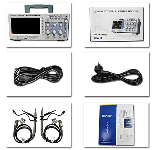
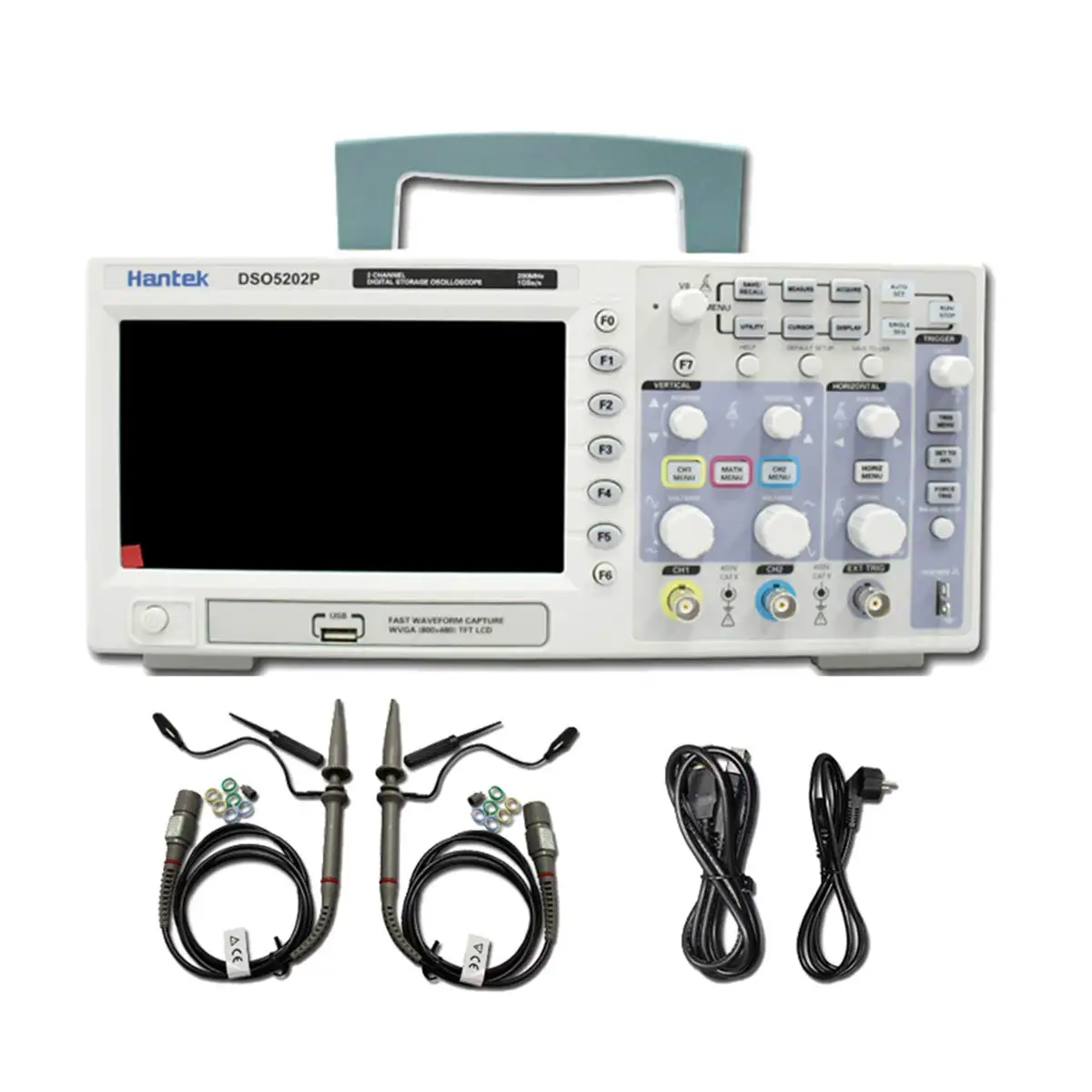
Product Packaging

Contact Us

We Recommend


New Arrivals
New products from manufacturers at wholesale prices


