
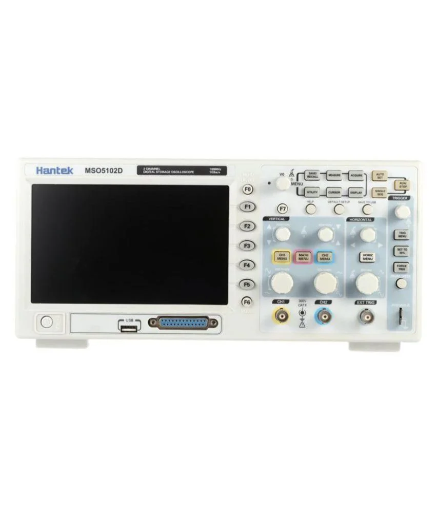
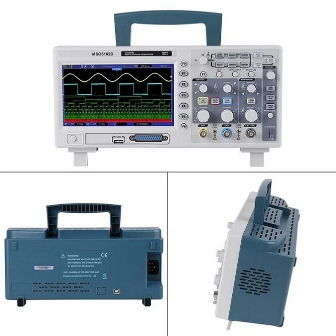
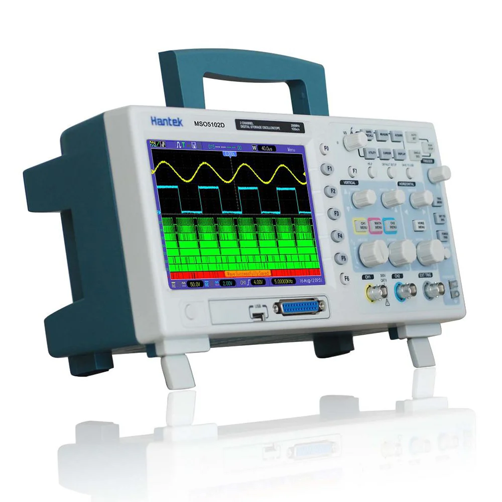
Hantek Mso5102d 100mhz Mixed Signal Oscilloscope 16 Channels Logic Analyzer 2 Channels Oscilloscope External Trigger
- Category: >>>
- Supplier: Shenzhen Robotlinking Technology Co. Ltd.
Share on (1600616970774):
Product Overview
Description

Product Description
Hantek Mso5102d 100mhz Mixed Signal Oscilloscope 16 Channels Logic Analyzer 2 Channels Oscilloscope External Trigger
.Feature
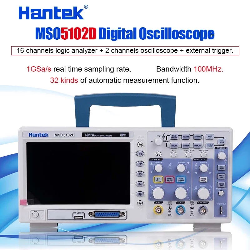
* 16 channels logic analyzer + 2 channels oscilloscope + external trigger.
* Big and clear display (7.0-inch color LCD, high revolution 800 x 480), clear lifelike waveform display.
* 1GSa/s real time sampling rate.
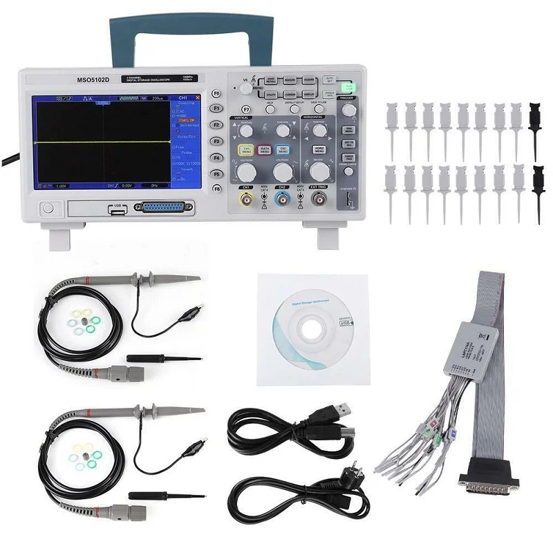
* USB host, support flash memory card storage and USB interface system upgrade.
* Ultrathin design, handy volume, easily portable.
* VGA Optional
Oscilloscope Function
* Bandwidth 100MHz.
* Each channel record length up to 1M.
* Real time sampling rate up to 1GSa/s.
* Powerful trigger function.
* 32 kinds of automatic measurement function.
Logic Analyzer Function
* 16 channels divided into 2 groups which is able to setup threshold level individually.
* Real time sampling rate up to 500MSa/s.
* Powerful trigger function: edge, duration, pulse width, code-type, queen, repeat.
Model | MSO5062D | MSO5102D | MSO5202D | |||
Bandwidth | 60MHz | 100MHz | 200MHz | |||
Sampling Rate Range | Max. 1GS/s | |||||
Waveform Interpolation | ( sin x) /x | |||||
Memory Depth | Single-channel: maximum 1M; Dual-channel: maximum 512K (4K, 16K, 40K optional) | |||||
SEC/DIV Range | 2ns/div to 40s/div | 4ns/div to 40s/div | ||||
Sampling Rate and Delay Time Accuracy | ±50ppm over any ≥1ms time interval | |||||
Delta Time Measurement Accuracy (full bandwidth) | Single-shot, Normal mode:± (1 sample interval +100ppm × reading + 0.6ns) | |||||
> 16 times above average (1 sampling interval + 100ppm × readings + 0.4 ns) | ||||||
Sampling interval = SEC/DIV÷200 | ||||||
A/D Converter | 8-bit resolution,each channel sampled simultaneously | |||||
VOLTS/DIV Range | 2mV/div to 5V/div at input BNC | |||||
Position Range | ±400mV (2mV/div ~20mV/div) | |||||
±2V (50mV/div ~200mV/div) | ||||||
±4V (500mV/div ~2V/div) | ||||||
±50V (5V/div) | ||||||
Bandwidth Limit (typical) | 20MHz | |||||
Low Frequency Response | ≤10Hz at output BNC(-3db) | |||||
Rising Time | ≤ 5.8ns | ≤ 3.5ns | ≤ 1.8ns | |||
Vertical Gain Accuracy | 3% for sample or average acquisition mode, 5V/div to 10mV/div; | |||||
4% for sample or average acquisition mode, 5mV/div to 2mV/div | ||||||
Trigger Types | Edge, Video, Pulse, Slope, Over time, Alternative,Code-type, Duration, Queue, Repeat | |||||
Trigger Source | CH1, CH2, EXT, EXT/5, AC Line | |||||
Input Coupling | DC, AC or GND | |||||
Input Impedance, DC Coupling | 1MΩ2% for 20pF3 pF | |||||
Probe Attenuation | 1X, 10X | |||||
Support Probe Attenuation Coefficients | 1X, 10X, 100X, 1000X | |||||
Math | +,-,x,÷,FFT | |||||
Cursors Measurement | Voltage difference between cursors: delt V Time difference between cursors: delt T Reciprocal of delt T in Hertz (1/ delt T) | |||||
Automatic Measurements | Frequency, Period, Mean, Peak-to-peak, Cycle RMS, Minimum, Maximum, Rise Time, Fall Time, Positive Width, Negative Width | |||||
Logic Analyzer Specification | ||||||
Sampled Channels | 16 ( divided into 2 groups) | |||||
Max. Input Impedance | 200K (C=10p) | |||||
Input Voltage Range | -60V~60V | |||||
Logic Threshold Range | -8V~8V | |||||
Max. Sample Rate | 500MHz | |||||
Compatible Input | TTL, CMOS, ECL | |||||
Sample Depth | 512KSample | |||||
Cursors | The difference between voltage cursors V; The difference between time cursors T; 1/T calculated by Hz. | |||||
Measurement | Period and Frequency | |||||
General Specification | ||||||
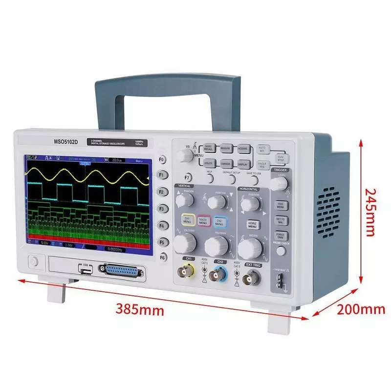
Display | 7"TFT 16K Color LCD, 800*480 dots | |||||
Dimension | 313(W)mm*142(H)mm*108(D)mm | |||||
Weight | 2.08kg (Not including the weight of package and accessories) | |||||
Customer Reviews

Company Profile

Exhibition

Certifications

Product Packaging

Contact Us

We Recommend


New Arrivals
New products from manufacturers at wholesale prices


