
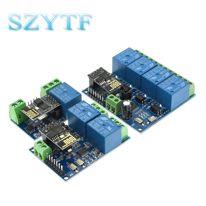
ESP8266 ESP 01 5V 4 Way WiFi Relay Module Things Smart Home Remote Control Switch ESP01 WIFI Wireless Module Phone APP
- Category: >>>
- Supplier: Shenzhen YTF Technology Co. Limited
Share on (1600618534803):
Product Overview
Description
Product Description

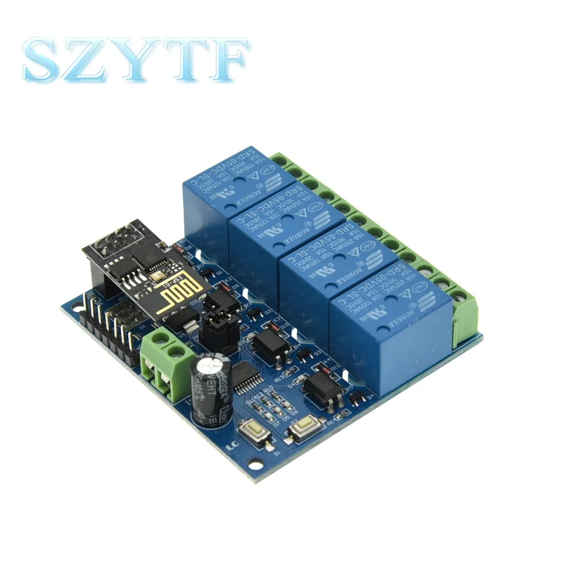
4 Way relay module 5v/12v

IN +, IN-: 5V power input;
5V, GND, TX, RX: UART serial port pins;
SWIM, PIN8, NRST: reserved MCU program download port.
Button S1: mode switch, the default is mode 1
Button S2: Restore factory settings
LED D1 / D2 / D3 / D4 (red light): relay working indicator light, when open the shell
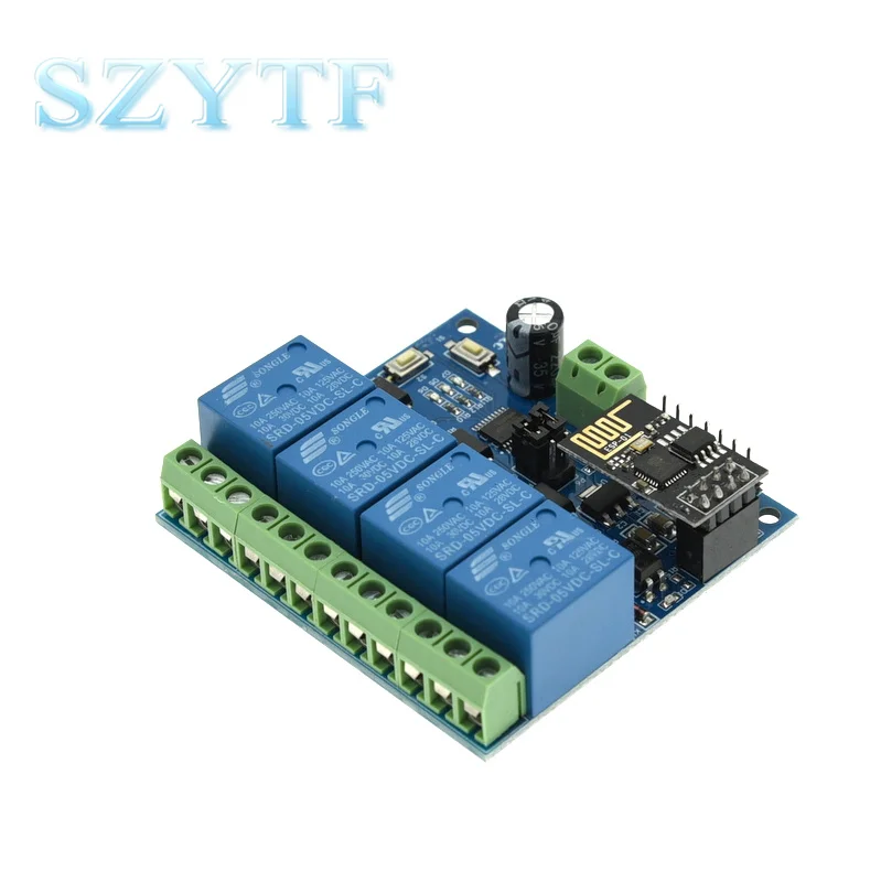
LED D7 (red light): Mode 1 indicator
LED D5 (blue light): Mode 2 indicator
LED D6 (green light): working status indicator, described as follows:
(1) When off, it means that it is self-configuring or loses connection with the router;
(2) When flashing at 0.5S, it means waiting for mobile phone APP to configure WIFI account and password for ESP-01 module;
(3) When the 2S flashes slowly, it means the configuration is completed, waiting for the establishment of a TCP connection with the mobile phone;
(4) Steady light indicates successful establishment of TCP connection with mobile phone.
Two reserved jumper caps: Please insert them to the bottom end (ie RX connected to RX1, TX connected to TX1) during normal use. Otherwise there may be interference).
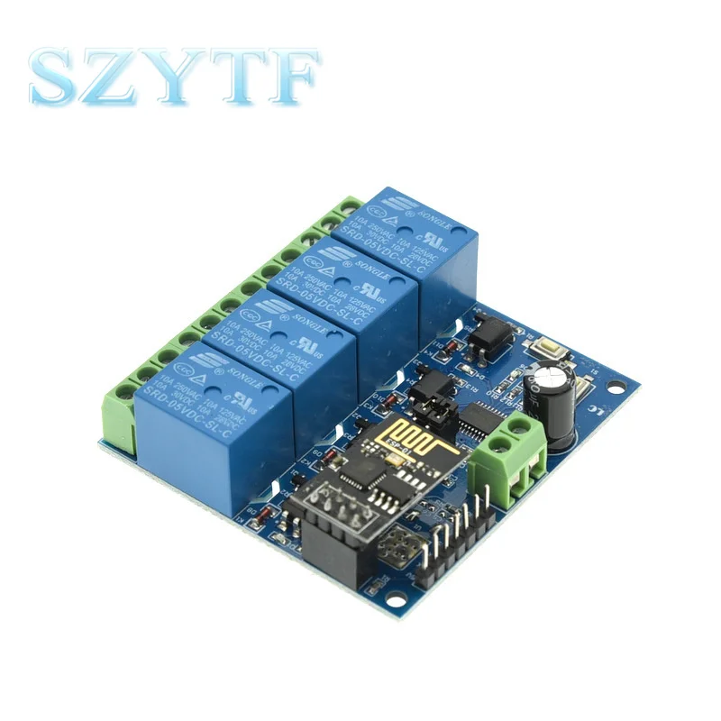
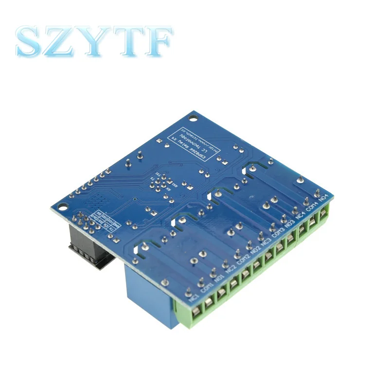
C0M1: public end;
NC1: Normally closed end, the relay is short-circuited with COM1 before pull-in, and hangs up after pull-in;
N01: Normally open, the relay hangs before pull-in, and short-circuit with COM1 after pull-in.
COM2: public terminal;
NC2: Normally closed end, the relay is short-circuited with COM2 before pull-in, and hangs up after pull-in;
NO2: Normally open, the relay hangs open before pull-in, and short-circuit with COM2 after pull-in.
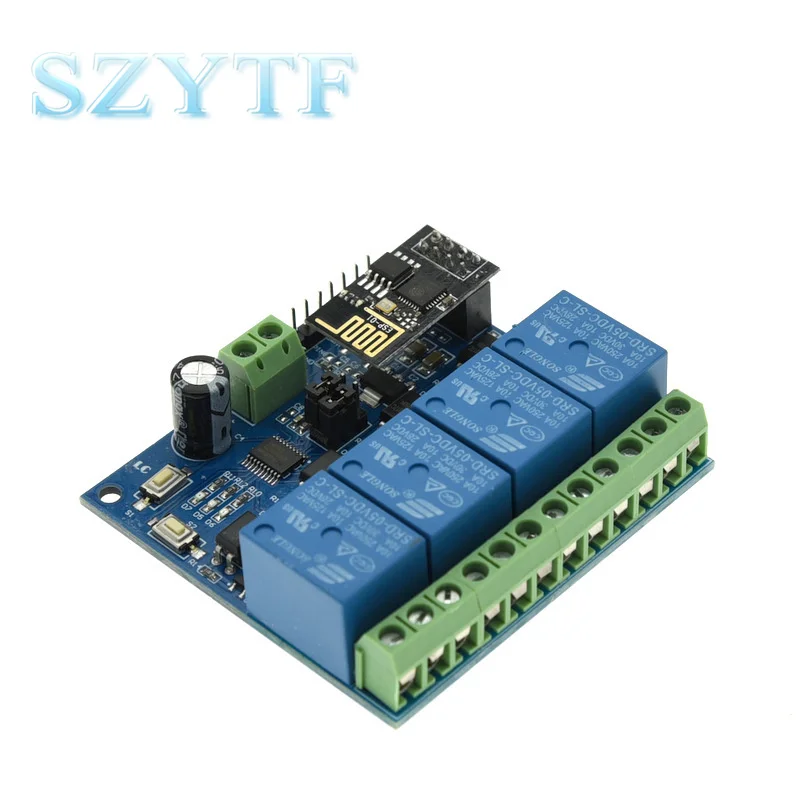
COM3: public terminal;
NC3: Normally closed end, the relay is short-circuited with COM3 before pull-in, and hang in the air after pull-in;
NO3: Normally open, the relay hangs open before pull-in, and short-circuit with COM3 after pull-in.
COM4: public terminal;
NC4: Normally closed end, the relay is short-circuited with COM4 before pull-in, and hangs up after pull-in
NO4: Normally open, the relay hangs before pull-in, and short-circuit with COM4 after pull-in.
Relay control command (hex hex format):
Turn on the first relay: A0 01 01 A2
Close the first relay: A0 01 00 A1
Open the second relay: A0 02 01 A3
Close the second relay: A0 02 00 A2
Open the third relay: A0 03 01 A4
Close the second relay: A0 03 00 A3
Turn on the fourth relay: A0 04 01 A5
Close the fourth relay: A0 04 00 A4
Our Services


Company Information


FAQ

Packaging & Shipping


We Recommend


New Arrivals
New products from manufacturers at wholesale prices


