
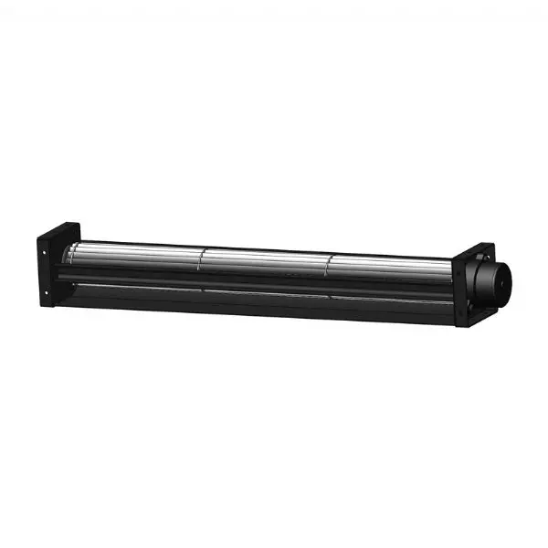
High Quality Energy Saving Centrifugal Fan For Electric Portable Heater
- Category: >>>
- Supplier: Pbm Motor And Fan(Suzhou) Co. Ltd.
Share on (1600651686538):
Product Overview
Description

Product Overview
Model No: PC3N30B24T
Motor Type: Φ37.5 (30D)
PRODUCT SPECIFICATIONS
1.General Characters
1-1 | Rated Voltage | 24 VDC |
1-2 | Operating Voltage | 16~28 VDC |
1-3 | Low-Start Voltage | 15 VDc |
1-4 | Rated Speed | 255ORPM |
1-5 | Input Current | 0.2A |
1-6 | Input Power | 4.8w |
1-7 | Acoustical Noise | 40dB(A) |
1-8 | Life Expectance | 50,00OHours(L10) At 40℃room, humidity 15%65%RH. |
1-9 | Direction of Rotation | Anti-clockwise seen on motor |
1-10 | Direction of Air Flow | All around |
1-11 | Insulation Class | Class B |
1-12 | Insulation Resistance | 50 Mega Ohm minimum at 500VDc Between frame and () terminal |
1-13 | Motor Protection | Locked rotor protection Polarity protection Automatic restart capability |
1-14 | Speed Control | Control inputO~10VDC |
1-15 | Dielectric Strength | 5mA maximum at 500VAC 5OHz five second Between frame and (+) terminal |
1-16 | Signal Output | No |
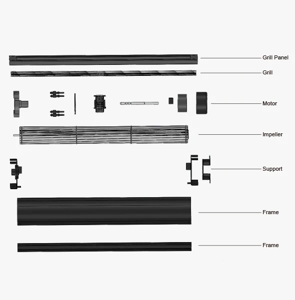
2.Mechanical Characters
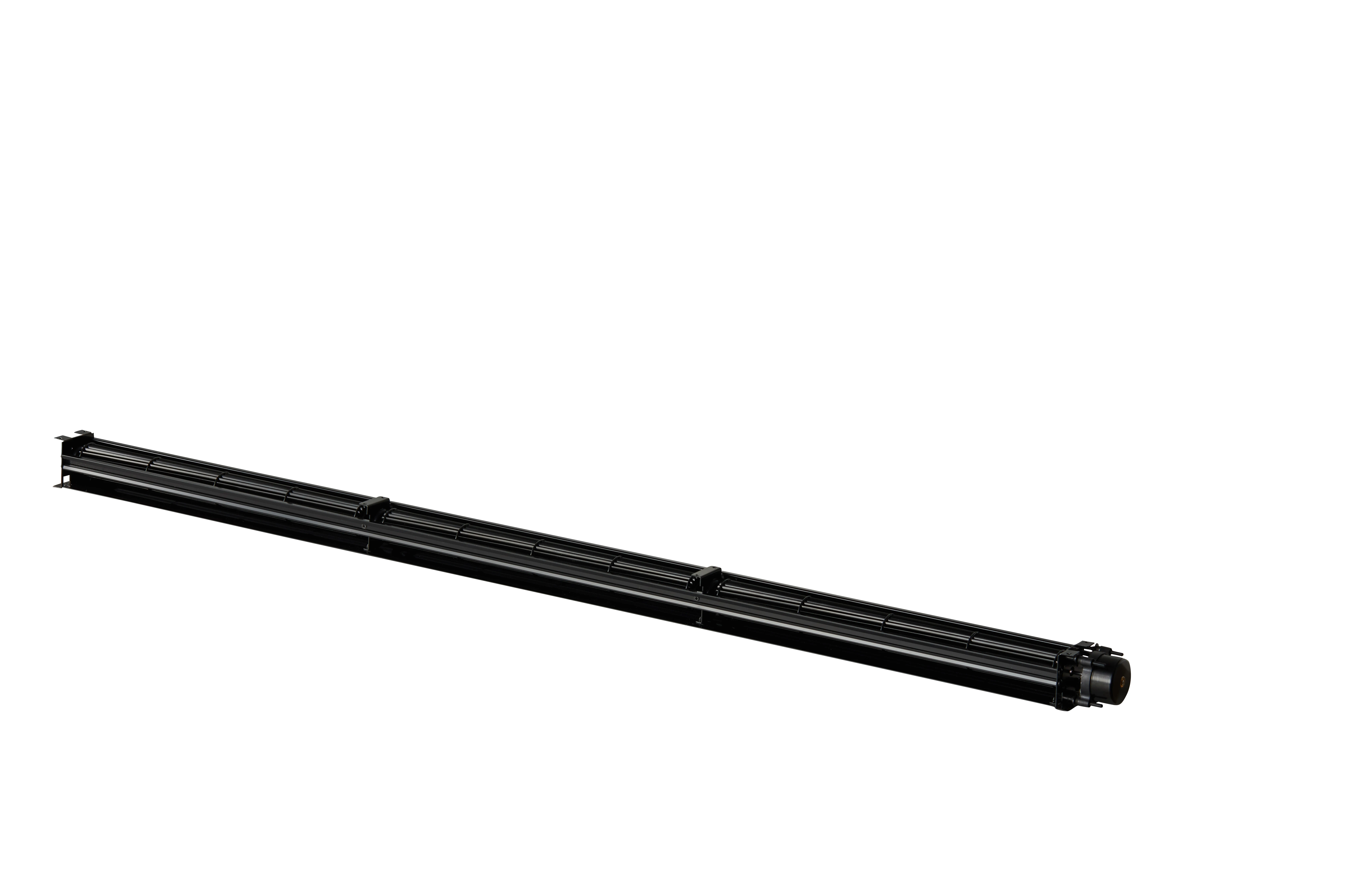
2-1 | Dimension | 48mm x 50mm x 705mm(see dimension drawing) |
2-2 | Material of Impeller | Steel |
2-3 | Number of Blades | 22 |
24 | Impeller Plate | Injection-moulded round sheet-metal plate |
2-5 | Mounting Position | Any |
2-6 | Surface of Rotor | Electrophoresis |
2-7 | Bearing System | NMB ball bearing |
2-8 | Lead Wire | Red , Black,White AWG22# |
2-9 | Weight | 837g |
2-10 | Package | Standard |
3.Electrical Protection
3-1 | Locked-rotor Protection | Over-current limiting circuit protects motor from damage at least for 72 hours oflocked rotor condition at rated voltage. |
3-2 | Maximum Current under Locked Rotor | A,Typical inrush current when the motor is trying to re-start under locked rotor conditions is 2~4 times the normal running current reoccurring and for 16~20% of restarting cycle period. B, If he CL function is used this restarting inrush current is about the same as the normal running current. |
3-3 | Reverse Polarity Protection | No damage if the positive and negative leads are reversed under maximum operation voltage conditions. |
3-4 | Over Voltage Protection | lhe circuit will be shut down automatically when input voltage over 30VDC.And re-started when Voltage down to 30VDC below. |
3-5 | Soft Start | In 5 seconds after power on and speed control voltage gets to 1.5v. |
4.Environmental Characters
4-1 | Operating Temperature | -25℃ to60℃ |
4-2 | Storage Temperature | -40℃ to75℃ |
4-3 | Operating Humidity | 5% to 90%RH |
4-4 | Storage Humidity | 5% to 95%RH |
4-5 | Drop Test | In minimum packaging condition fan withstand each one drop of three faces from 30cm distance height onto 10mm thickness of wooden board. |
4-6 | Vibration Test | Sine Wave. Displacement amplitude: 0.75mm (Equivalent 10G). Frequency Range: 10Hz~-55Hz/ 30 sec.55Hz~10Hz / 30 sec Linear Scanning 120 Cycle Endurance timer per axis: 2 Hours Orientation:X,Y,Z. |
4-7 | Shock Test | Apply peak acceleration 50g and keep duration of the pulses for l1ms (Half sine wave) |
4-8 | RoHS | All the material meets RoHS standard. |
5.Airflow Curve

Testing Condition
Input Voltage----Operating voltage (24VDC)
Temperature-----Room temperature
Humidity---------65%RH
Test distance-----1m
Temperature-----Room temperature
Humidity---------65%RH
Test distance-----1m
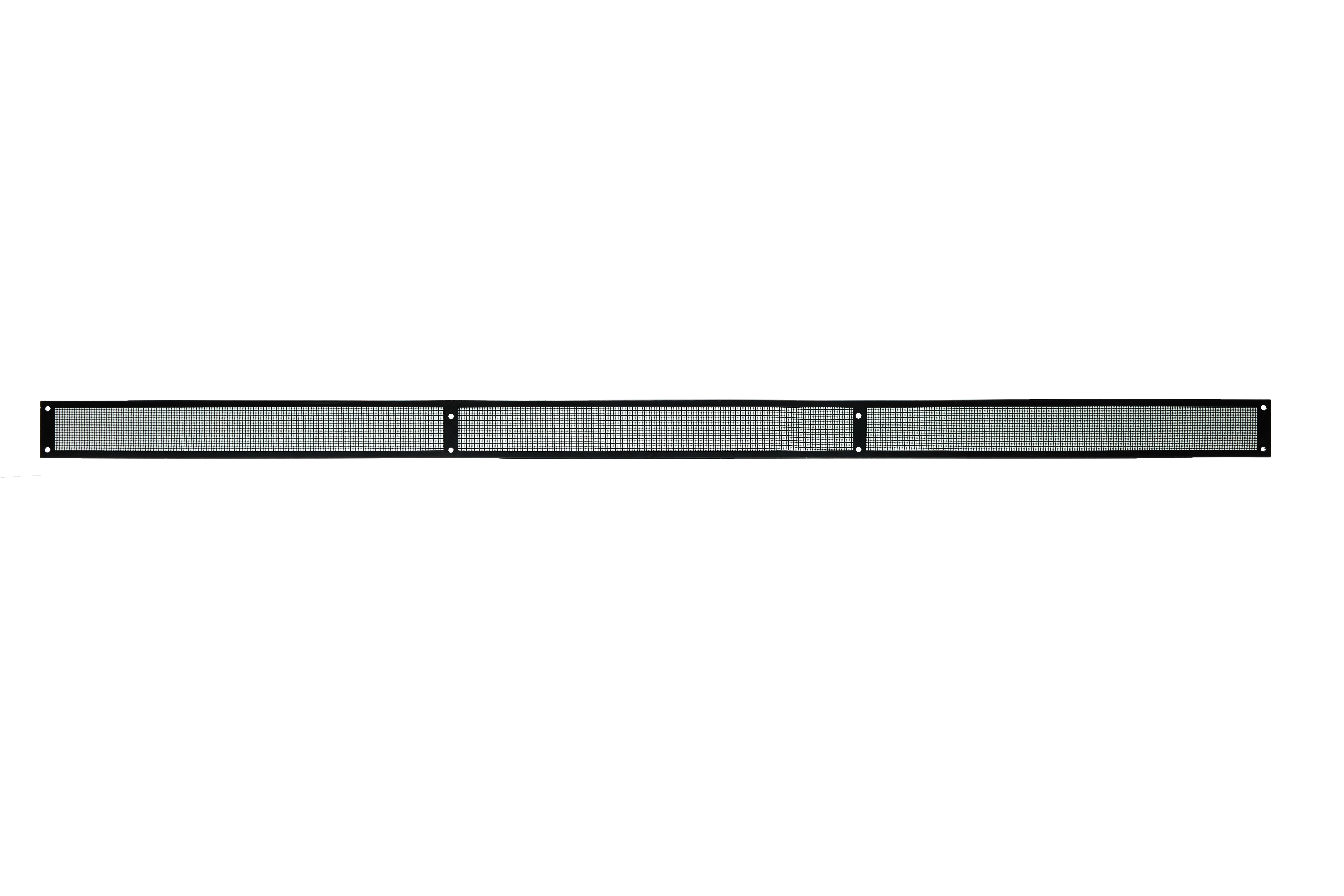
6.Outline Drawing

Note
1. Connection line 3X (Red, Black, White AWG22#);
Red=+, White=0-10VDC/PWM, Blue=GND.
Red=+, White=0-10VDC/PWM, Blue=GND.
7.Connection Diagram

8.Special Accessory

Bearing
NMB Bearing,Model:L-940ZZ,
Specification as following:
Specification as following:

9.Safety Requirements
1. Make sure that the metal casing of the stator connected to the ground before being powered on.
2. If the fan doesn’t work after been powered on, please check the speed control input voltage, it may not be well connected. To prevent the suddenly start of the fan to hurt hands or other personal injury; do not touch the impellers or rotor when the power is on.
3. Fan needs a few seconds to start after being powered on. To prevent personal injury, do not touch the impellers or rotor when the power is on or in a low speed.
4. Unless they are instructed by the person(s) responsible for their safety, those who are lack of physical, mental or sensory capacities and proper practical experience or expertise cannot use this appliance. Please do not let the children play with this product.
5. If the power cord be damaged, the power cord must be replaced by the manufacturer in order to avoid accident of the proxy service personnel or the equivalent qualification maintenance personnel.
6. As an integral part of the fan, this DC motor cannot be used alone without impeller or load.
7. Please carefully read this technical specification before using the product.
Related Products
Products Description


Company Profile

Certifications

FAQ

We Recommend


New Arrivals
New products from manufacturers at wholesale prices


