
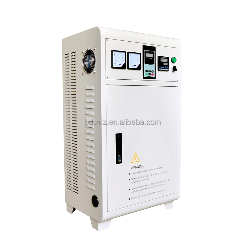
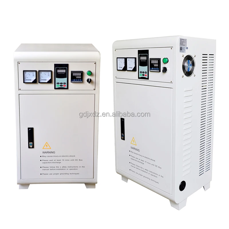
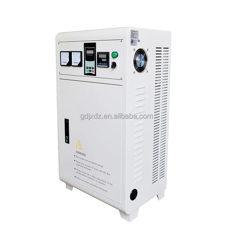
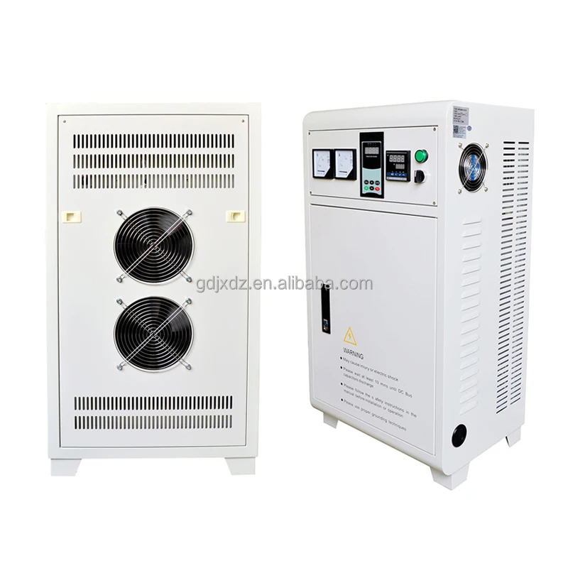
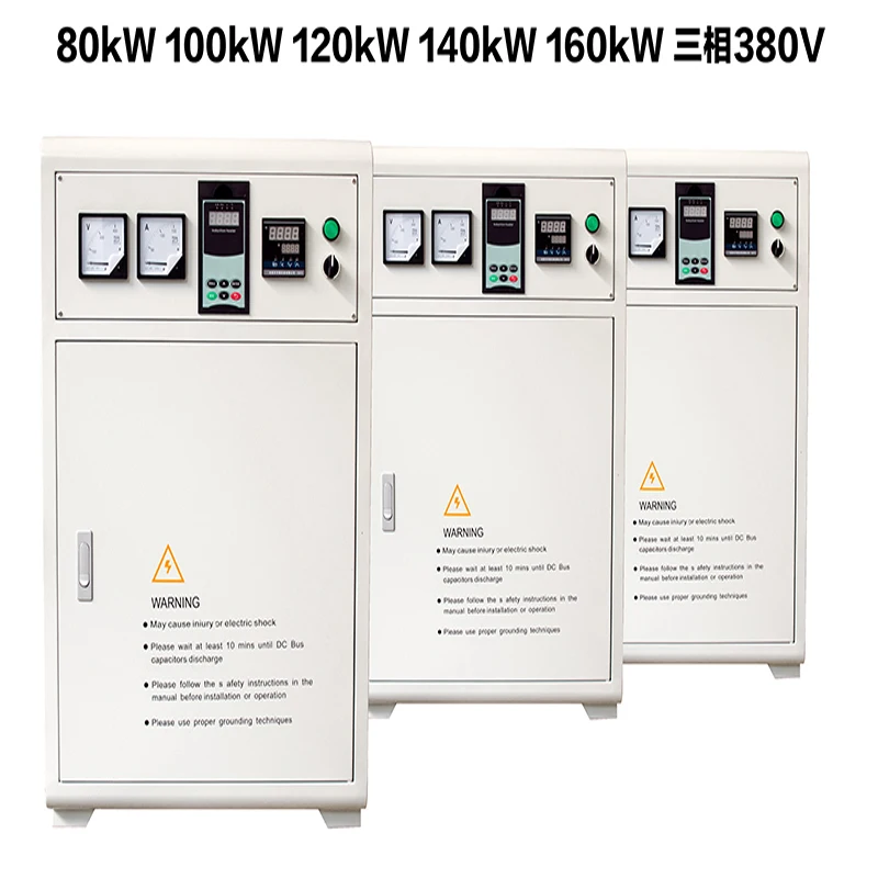
Plastic equipment induction heater Conversion From Coal to Electricity Electromagnetic Heating Cabinet
- Category: >>>
- Supplier: Guangdong Jiangxin Electronic Technology Co. Ltd.
Share on (1600979133772):
Product Overview
Description
Product feature 1
Integrated with digital core controller and German infineon IGBT frequency conversion driver, intelligent temperature control module control hot air output, over current, over temperature protection;Heating coil short circuit, open circuit protection.
Product feature 2
Variable frequency output can automatically adjust the output power according to the temperature; the cable itself does not generate heat, and can withstand the high temperature below 1000 degrees Celsius, the design life of the main engine is more than 10 years, the heating system basically has no maintenance cost in the later stage.Under the same condition, it is more than 30% more energy efficient than coal, and 60% more energy efficient than natural gas and fuel oil.
Product feature 3
Electromagnetic induction heating, no open fire, no fire hazard, safe and stable;No waste gas, no oxygen consumption, no
pollution.

Products Description

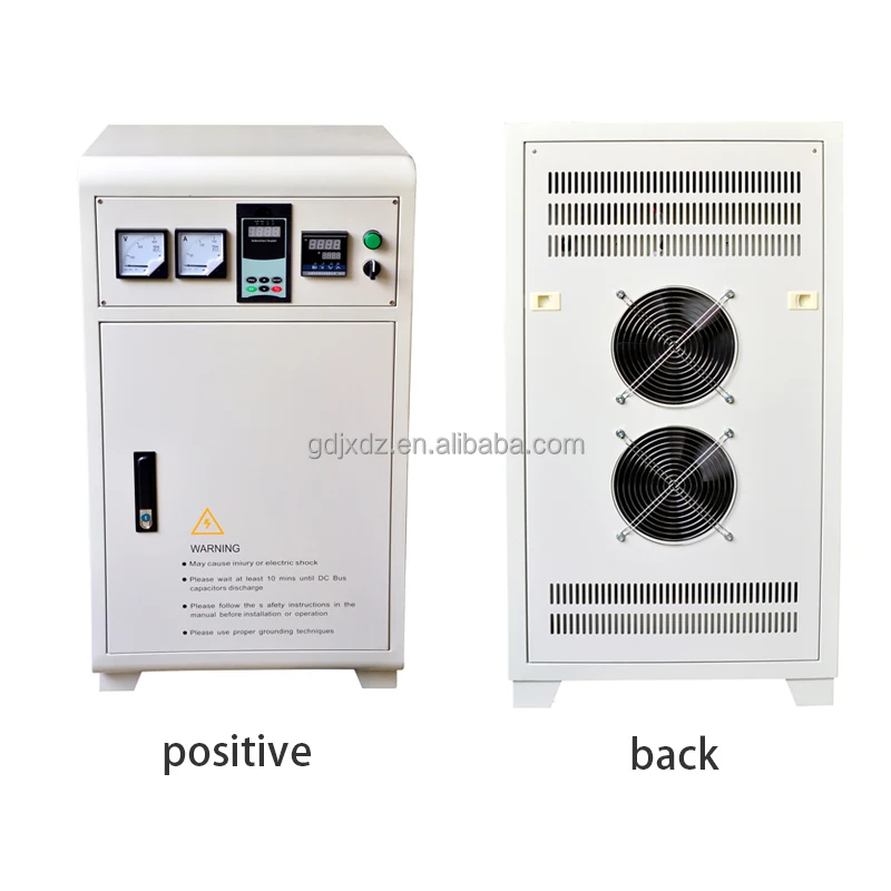
1,Connect the power supply voltage of the cooling fan, but connect the 220V power when the fan is 220V, and connect the 380V power when the fan is 380V
2,Connected with cooling fan 220V / 380V (depending on the user, generally 380V)
3,When the external cooling fan is DC 24V, this interface is a switch that controls the 24V fan to work or stop. The two ends of the interface are actually the normally closed contact points of the relay output on the motherboard.
4,Dual AC 24V power supply (choose 4 or 5 when making half bridge)
5,Dual AC 24V power supply (choose 4 or 5 when making half bridge)
6,Single AC 16V power supply
7,Power indicator (red)
8,Work indicator light, flashing during standby, and always on (green) during work
9,External indicator light, led to the LED interface outside the chassis
10,The soft start interface is connected to the R / s interface outside the chassis (can be set to open or close work through F-20, factory default close work, open stop status
11,Finely adjust the power potentiometer. When there is a large deviation in power, this potentiometer can be adjusted
appropriately.
12,32-bit high-speed DSP processor
13,Externally connected programmable operating display
14,Isolated RS485 communication interface
15,External load temperature detection interface 1, with accuracy of ± 1 ° C (maximum 150 ° C) single channel, default 1 is used to measure external working temperature
16,External load temperature detection interface 2, with accuracy of ± 1 ° C (maximum 150 ° C)
17,Multi-function input interface (set by F-20)
(1)10K input for external connection potentiometer, can adjust the power range from 20% to 100%
(2)Externally connected PID input (0 ~ 5V) input Do infrared thermometer or thermocouple conversion voltage 0 ~ 5V input to achieve the display temperature and control power size (up to 1000ºC can be measured and displayed)
18,Connect the high-frequency Mutual inductor and pay attention to the direction. If the direction is reversed, the power is very small
19,IGBT module drive (when doing half bridge, choose 19, 20 or 23, 24)
20,IGBT module drive (when doing half bridge, choose 19, 20 or 23, 24)
21,Connected to high voltage DC bus
22,IGBT temperature sensor interface
23,IGBT module drive (when doing half bridge, choose 19, 20 or 23, 24)
24,IGBT module drive (when doing half bridge, choose 19, 20 or 23, 24)
25,Connected to high voltage DC bus
26,RS485 communication interface, connect A ,B
27,Externally connected K-type thermocouple
28,Externally connected 12V relay drives other required loads, synchronized with the fan start / stop of the machine
Applications
Plastic rubber industry | Such as: electromagnetic heating projects, rubber machines, pelletizers, vulcanizers, extruders; |
Pharmaceutical and chemical industry | Such as: medical machinery steam sterilizers, medical infusion bags, plastic equipment production lines, liquid heating pipelines in the chemical industry, etc . |
Energy and food industry | Such as: heating of crude oil transportation pipelines, food machinery, hot air pipeline drying furnaces, tea processing equipment and other equipment that requires electrical heating |
Building materials industry | gas pipe production line, plastic pipe production line, PE plastic hard flat net, geonet net unit, automatic blow molding machine, PE honeycomb board production line, single and double wall corrugated pipe extrusion production line, composite air cushion film unit, PVC hard Tube, PP extrusion transparent sheet production line, extruded polystyrene foam tube, PE winding film unit; |
Energy saving reconstruction | Aluminum-plastic plate roller oven electromagnetic heating project, energy-saving transformation of various plastic machines, etc. |
Company Profile

Guangdong Jiangxin Electronic Technology Co., Ltd.
Guangdong Jiangxin Electronic Technology Co., Ltd. is an extraordinary energy-saving solution provider. Its products and solutions are widely used in heating, chemical industry, mold manufacturing, plastic machinery, food processing and other industries. The company has a strong product R & D and engineering technology team, which is committed to transforming wisdom into excellent products and services, meeting the needs of different customers and continuously creating value for customers.
Jiangxin electromagnetic is a brand of Guangdong Jiangxin Electronic Technology Co., Ltd. and is committed to promoting the sustainable and steady development of China's energy conservation and emission reduction. With its comprehensive advantages in the field of electromagnetic induction heating, we strive to become a leader in the industry. Taking improving the earth's natural environment as its own responsibility, meeting the principle of social sustainable development, and building reliable and stable green energy-saving products and solutions for users are the key to maintaining the advantages of the company.
Adhering to the purpose of "scientific and technological innovation and military quality", we solemnly promise that the service life of the whole machine is guaranteed for ten years, one year free maintenance and lifelong maintenance. We believe that with your care and support and our tireless efforts, Jiangxin Electronics will enter a brilliant future with you.

Certifications

Product Shipping

FAQ
1.How can I get the price?
-We usually quote within 24 hours after we get your inquiry(Except weekend and holidays).
-If you are very urgent to get the price, please email us or contact us in other ways so that we can offer you a quote.
-If you are very urgent to get the price, please email us or contact us in other ways so that we can offer you a quote.
2. Can I buy samples placing orders?
-Yes.Please feel free to contact us.
3.What is your lead time?
-It depends on the order quantity and the season you place the order.
-Usually we can ship within 7-15 days for small quantity,and about 30 days for large quantity.
-Usually we can ship within 7-15 days for small quantity,and about 30 days for large quantity.
4.What is your payment term?
-T/T,Western Union,MoneyGram,and Paypal.This is negotiable.
5.What is the shipping method?
-It could be shipped by sea,by air or by express(EMS,UPS,DHL,TNT,FEDEX and ect).
Please confirm with us before placing orders.
6.How do you make our business long-term and good relationship?
-1. We keep goodquality and competitive price to ensure our customers benefit ;
-2. We respect every customer as our friend and we sincerely do business and make friends with them,no matter where they come from.
-2. We respect every customer as our friend and we sincerely do business and make friends with them,no matter where they come from.
 VR
VR
We Recommend


New Arrivals
New products from manufacturers at wholesale prices


