D.UBEC Dual Output Ammeter Power Module Supports 4 18S Input with Hall for Aircraft RC Model Flight Control
- Category: >>>
- Supplier: Hubei Jingzhou Mayatech Intelligent Technology Co. Ltd.
Share on (1601016022985):
Product Overview
Description
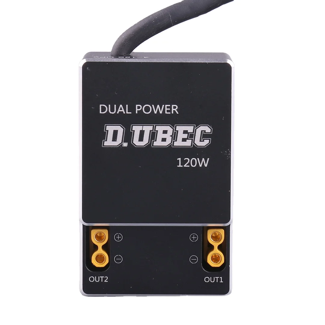
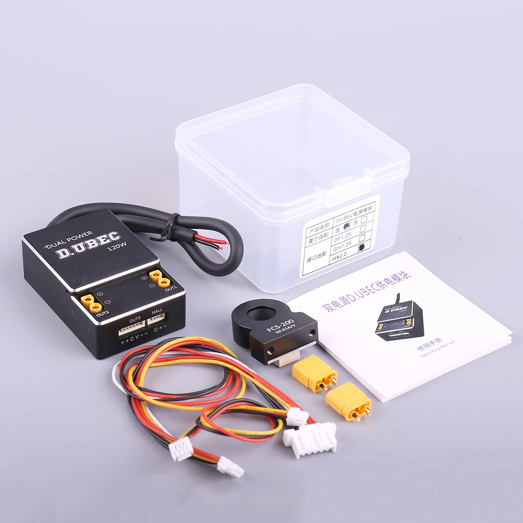
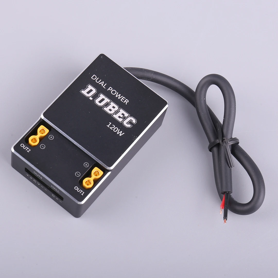
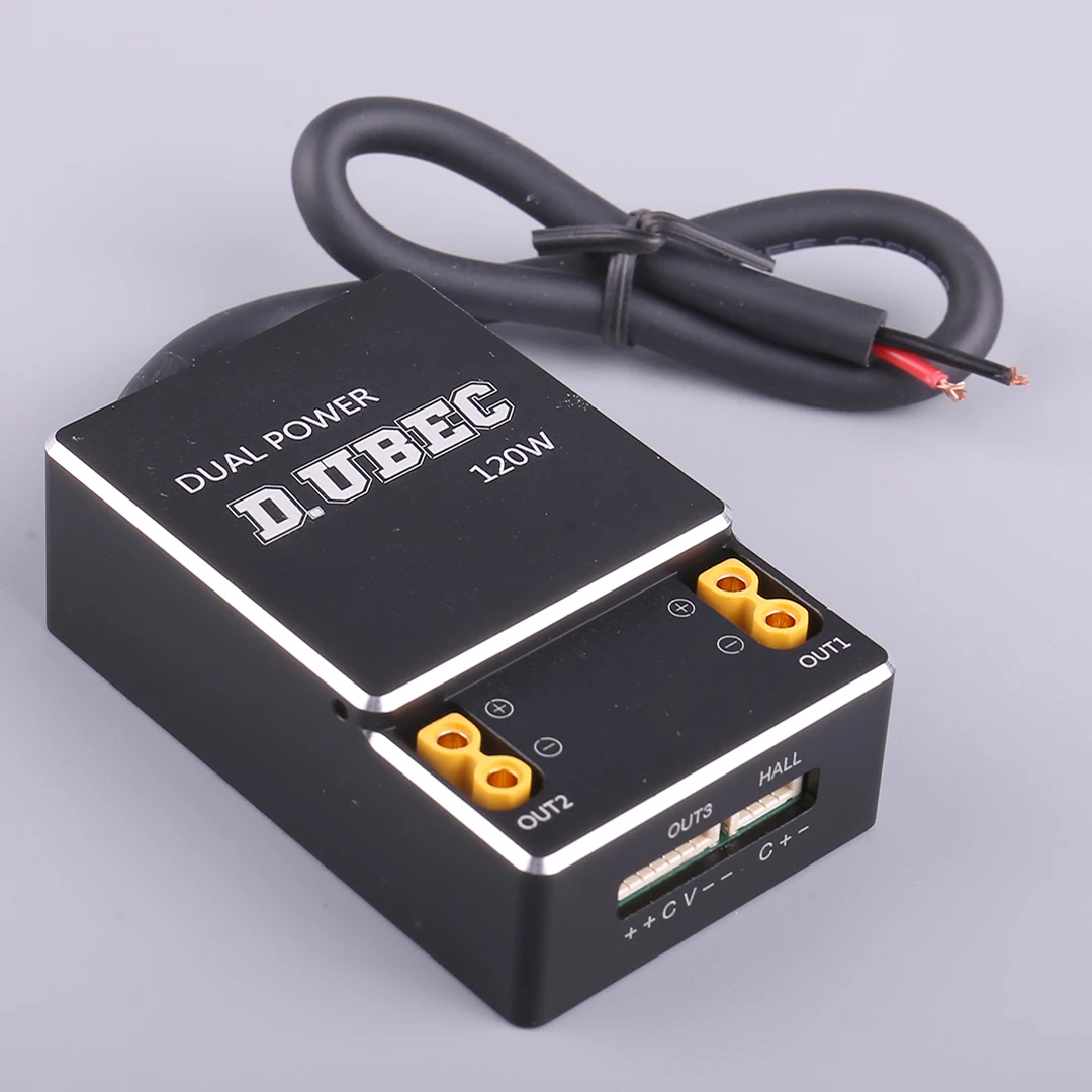
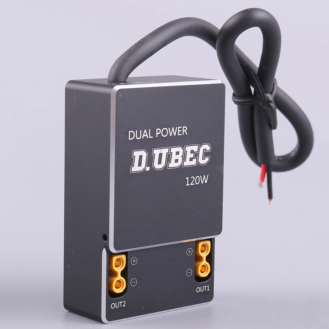
D. UBEC Dual Output Ammeter Power Module


Cable Example


Product features
* The main function of this module is a two-stage DC step-down power supply module. The first stage supports up to 80V input and 12.3V/10A output, which is used for 12V equipment power supply. The second stage is a secondary voltage reduction of 5.3V/5A output, providing electricity for 5V equipment. The module has the characteristics of high voltage resistance, high power, and strong overload resistance. The first level instantaneous overload can reach 33A. Secondary withstand voltage of 60V, dual protection for secondary voltage reduction. Even if the primary input is not higher than 60V, the secondary can operate normally to ensure the normal operation of the secondary terminal equipment.
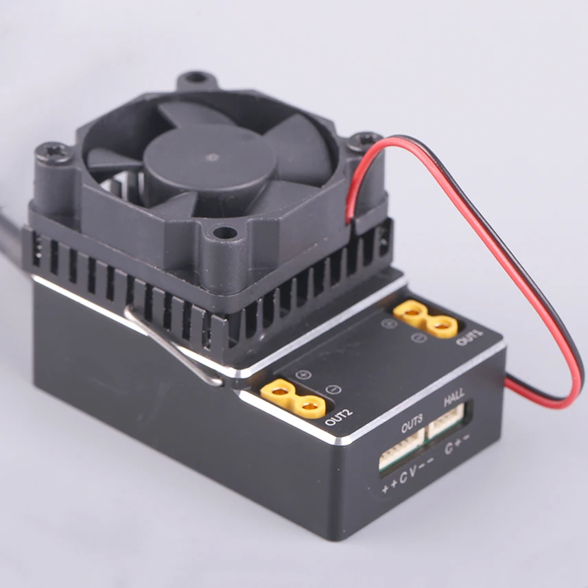
* The module has a voltage and current detection function and is equipped with a low-temperature drift high-precision voltage sampling resistor. It can perform voltage division detection on the input voltage and output it through OUT3. The current detection is achieved through an external Hall sensor, and the Hall sensor interface uses 5VLDO for precise voltage stabilization output.
* The overall CNC aluminum shell of the module has good heat dissipation, and an external heat sink hook hole is reserved. When used above 60% of the rated power, the module generates a large amount of heat. It is recommended to install an external heat sink fan for forced heat dissipation and cooling.
Product parameters
Input: 4-18S LiPo (Max 80V)
Output: 12.3V/10A
2 # Output: 12.3V or 5.3V (internal jumper selection)
3 # Output: 5.3V/5A
Conversion efficiency:>90%
No load current: ≤ 20mA
DC voltage reduction type: PWM switch type
Voltage detection voltage ratio: 24.28
Size: 55 * 35 * 18mm
Weight: 70 grams
FCS200 Hall sensor parameters (Optional parts)
Power supply: 5V
Range: 200A
Output ratio: 60.61A/V
Current and voltage detection settings
The basic principle of current detection is to use Hall sensors to sense the magnetic field strength around the target cable and output a proportional 0-3.3V analog voltage signal for flight control to perform ADC detection. After the flight control detects the voltage value, the result is multiplied by the proportional value to obtain the actual current value.
The basic principle of voltage detection is to divide the voltage at the input power terminal in a certain proportion and output a 0-3.3V analog voltage signal. After the flight control detects the voltage value, the result is multiplied by the voltage division ratio to obtain the actual voltage value.
* The above figure shows the basic setting method of this ammeter in MP. According to the detection principle, the two key factors that affect the normal operation of the detection are the pin PIN used for connecting the ammeter to the flight control and the proportional value of the detection. The pin PIN is quickly selected through the APM version field, while the only parameters related to the ammeter itself are the voltage divider and amps per volt. These two parameters can only be manually entered by selecting the sensor field as other.
* In general, if the above settings are correct, the ammeter detection can work normally. However, due to the current and voltage signals being micro current signals, the contact resistance and line length of the plug-in are sensitive to the line impedance,so the final value is generally low. You can input the actual voltage value of the current battery in the measurement of battery voltage column. The system will automatically calculate the current voltage divider value based on the input value,which is generally slightly larger than 15.7, If there is a significant difference, it indicates that the pin number may not have been selected correctly or there may be other issues. Please abandon calibration and reset the voltage divider to 15.7 and troubleshoot other faults before recalibrating.
* Current sensors require professional equipment to be calibrated under specific conditions, and ordinary users do not recommend calibration.
Note
* 1. When the equipment is powered on or powered off, the principle of quick on and quick off should be followed. Do not shake the contact at the critical point, otherwise it is easy to generate self induced electromotive force superposition in the circuit and breakdown the equipment;
* 2. In a multi device common ground system, even if the ground wire of the power supply main line is not connected! In the case where only the positive pole is connected, the ground wire of the signal line can also form a circuit. If the main power supply current is large, it will damage or even burn out the parts with lower current resistance in the ground wire circuit system.Therefore, when the equipment is powered on, the principle of connecting the ground wire first should be followed as much as possible;
* 3. This device belongs to DC power supply equipment. Before powering on any connected equipment, please carefully check the polarity, otherwise there may be a risk of short circuit and burning of the equipment;
* 4. When the device is used with a safe voltage exceeding 36V, there is a risk of electric shock to the human body. Please
follow the safety electricity regulations when using this device:
* 5. When using this device in a humid environment, please pay attention to taking moisture-proof measures;
* 6. This device generates a large amount of heat during operation, so it is necessary to take measures such as heat dissipation,ventilation, and anti scalding.
* The main function of this module is a two-stage DC step-down power supply module. The first stage supports up to 80V input and 12.3V/10A output, which is used for 12V equipment power supply. The second stage is a secondary voltage reduction of 5.3V/5A output, providing electricity for 5V equipment. The module has the characteristics of high voltage resistance, high power, and strong overload resistance. The first level instantaneous overload can reach 33A. Secondary withstand voltage of 60V, dual protection for secondary voltage reduction. Even if the primary input is not higher than 60V, the secondary can operate normally to ensure the normal operation of the secondary terminal equipment.
* The module has a voltage and current detection function and is equipped with a low-temperature drift high-precision voltage sampling resistor. It can perform voltage division detection on the input voltage and output it through OUT3. The current detection is achieved through an external Hall sensor, and the Hall sensor interface uses 5VLDO for precise voltage stabilization output.
* The overall CNC aluminum shell of the module has good heat dissipation, and an external heat sink hook hole is reserved. When used above 60% of the rated power, the module generates a large amount of heat. It is recommended to install an external heat sink fan for forced heat dissipation and cooling.
Product parameters
Input: 4-18S LiPo (Max 80V)
Output: 12.3V/10A
2 # Output: 12.3V or 5.3V (internal jumper selection)
3 # Output: 5.3V/5A
Conversion efficiency:>90%
No load current: ≤ 20mA
DC voltage reduction type: PWM switch type
Voltage detection voltage ratio: 24.28
Size: 55 * 35 * 18mm
Weight: 70 grams
FCS200 Hall sensor parameters (Optional parts)
Power supply: 5V
Range: 200A
Output ratio: 60.61A/V
Current and voltage detection settings
The basic principle of current detection is to use Hall sensors to sense the magnetic field strength around the target cable and output a proportional 0-3.3V analog voltage signal for flight control to perform ADC detection. After the flight control detects the voltage value, the result is multiplied by the proportional value to obtain the actual current value.
The basic principle of voltage detection is to divide the voltage at the input power terminal in a certain proportion and output a 0-3.3V analog voltage signal. After the flight control detects the voltage value, the result is multiplied by the voltage division ratio to obtain the actual voltage value.
* The above figure shows the basic setting method of this ammeter in MP. According to the detection principle, the two key factors that affect the normal operation of the detection are the pin PIN used for connecting the ammeter to the flight control and the proportional value of the detection. The pin PIN is quickly selected through the APM version field, while the only parameters related to the ammeter itself are the voltage divider and amps per volt. These two parameters can only be manually entered by selecting the sensor field as other.
* In general, if the above settings are correct, the ammeter detection can work normally. However, due to the current and voltage signals being micro current signals, the contact resistance and line length of the plug-in are sensitive to the line impedance,so the final value is generally low. You can input the actual voltage value of the current battery in the measurement of battery voltage column. The system will automatically calculate the current voltage divider value based on the input value,which is generally slightly larger than 15.7, If there is a significant difference, it indicates that the pin number may not have been selected correctly or there may be other issues. Please abandon calibration and reset the voltage divider to 15.7 and troubleshoot other faults before recalibrating.
* Current sensors require professional equipment to be calibrated under specific conditions, and ordinary users do not recommend calibration.
Note
* 1. When the equipment is powered on or powered off, the principle of quick on and quick off should be followed. Do not shake the contact at the critical point, otherwise it is easy to generate self induced electromotive force superposition in the circuit and breakdown the equipment;
* 2. In a multi device common ground system, even if the ground wire of the power supply main line is not connected! In the case where only the positive pole is connected, the ground wire of the signal line can also form a circuit. If the main power supply current is large, it will damage or even burn out the parts with lower current resistance in the ground wire circuit system.Therefore, when the equipment is powered on, the principle of connecting the ground wire first should be followed as much as possible;
* 3. This device belongs to DC power supply equipment. Before powering on any connected equipment, please carefully check the polarity, otherwise there may be a risk of short circuit and burning of the equipment;
* 4. When the device is used with a safe voltage exceeding 36V, there is a risk of electric shock to the human body. Please
follow the safety electricity regulations when using this device:
* 5. When using this device in a humid environment, please pay attention to taking moisture-proof measures;
* 6. This device generates a large amount of heat during operation, so it is necessary to take measures such as heat dissipation,ventilation, and anti scalding.

Company Profile


FAQ
1. who are we?
We are based in HuBei jingzhou, China。
Mayatech committed to building the largest professional one-stop model parts procurement platform.
our has over 300 independently developed products, including multiple patents and CE certified products.
Mayatech committed to building the largest professional one-stop model parts procurement platform.
our has over 300 independently developed products, including multiple patents and CE certified products.
2.Are you a manufacturer?
Yes, as the original factory supplier in Chinese mainland, we're specialized in
doing and selling hobby accessories since 2011.
doing and selling hobby accessories since 2011.
3.what can you buy from us?
Motor, Engine, Remote control, Receiver, Charger,Flight control, Propeller, Servo, ESC,Camera, GPS, Tools.(All spare parts for Models, UAV, and remote-controlled toys)
4.How to order?
Step 1. please tell us product items and quantity you need.
Step 2. we will make a Pl with shipping cost for your reference.
Step 3. payment can be arranged after we confirm everything in details.
Step 4. we will deliver the goods within stipulated time.
Step 2. we will make a Pl with shipping cost for your reference.
Step 3. payment can be arranged after we confirm everything in details.
Step 4. we will deliver the goods within stipulated time.
5.What are the payment methods?
PayPal, TT, Western Union, Moneygram, Escrow, etc. Beside, we accept
Alibaba Trade
Alibaba Trade
6.What's the delivery time?
1.Sample Order:1-3 days after receipt of the full payment.
2.Stock Order:3-7 days after receipt of the full payment.
3.OEM/ODM Order:15-30 days after receipt of the deposit.
2.Stock Order:3-7 days after receipt of the full payment.
3.OEM/ODM Order:15-30 days after receipt of the deposit.
7.Can you know more?
Welcome to send TM anytime.
We Recommend

New Arrivals
New products from manufacturers at wholesale prices