JCZ LMCV4 Fiber / Co2 Laser Marking Control Card Ezcad Control Card
- Category: >>>
- Supplier: Anhui Codos Laser Technology Development Co. Ltd.
Share on (1601052575405):
Product Overview
Description

Products Description
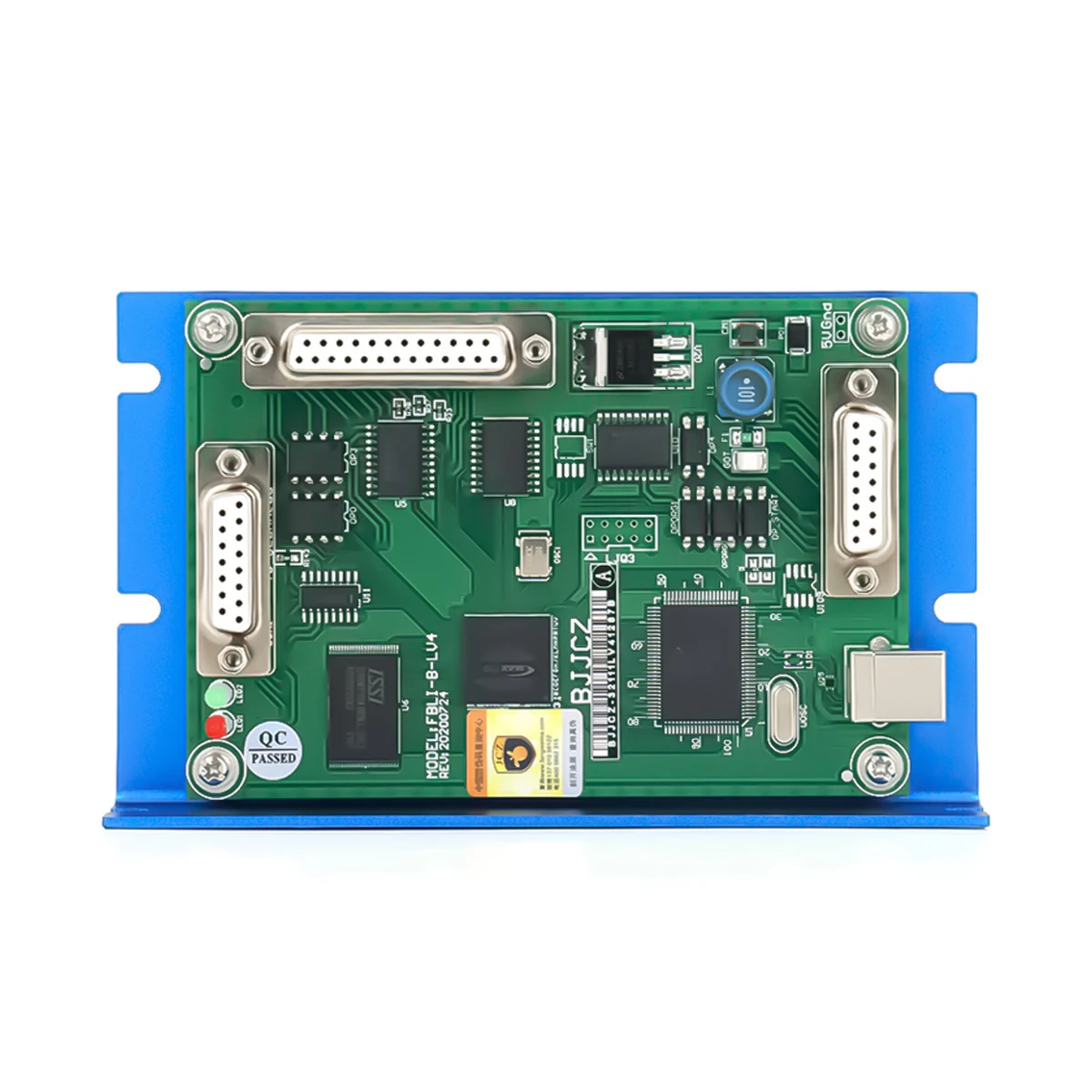
JCZ LMCV4 Fiber / Co2 Laser Marking Control Card
1. Use the DB25 socket connector, Can be directly connected pulsed fiber laser.
2. The galvanometer control signal is digital and can be directly connected to a universal digital galvanometer.
3. Extended axis (stepper motor/servo motor) output: It can output the direction/pulse signal of two channels to control the stepper motor (or servo motor), which can be used for shaft rotation or splicing.
4. 6 universal input digital signals (TTL compatible). XORG0 (IN14) (IN15) where IN0~IN3 are designated as laser state input signals are quoted by CON2 (Laser ST0~Laser ST3).
5. 2 general purpose output digital signals (TTL compatible). OUT4, OUT5 are TTL outputs;
6. ReMark (cache content repeated marking) Signal: used for marking the same content, requiring high-speed marking.
7. Compatible with USB2.0.

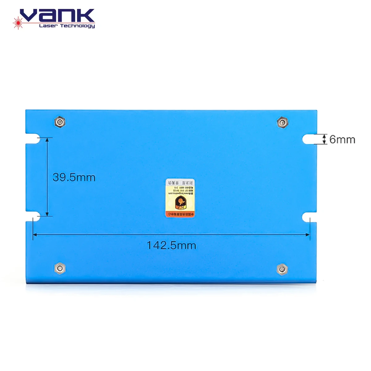
Dimension

Interface Definition

CON1: DB15 Galvanometer Control | ||||||||
Pin NO. | Name | Description | ||||||
1, 9 | CLK-/CLK+ | Clock signal ± | ||||||
2, 10 | SYNC-/SYNC+ | Sync signal ± | ||||||
3, 11 | XChannel-/XChannel+ | Galvanometer X signal ± | ||||||
4, 12 | Y Channel- /YChannel + | GalvanometerY signal ± | ||||||
5, 13 | NULL | Reserved | ||||||
6, 14 | NULL | Reserved | ||||||
7 | NULL | Reserved | ||||||
8, 15 | GND | Ground | ||||||
CON2: DB25 Laser Control | ||||||||
Pin NO. | Name | Description | ||||||
1 | XORG0 | The home signal of extension axis X. To use this pin just connect it and GND to a switch. In software In14 represents this pin. | ||||||
2 | GIN15 | General input in15. using GND as a reference ground | ||||||
2, 10 | Out4, Out5 | General Output Out 4-0ut 5. using GND as reference ground. They are all TTL output | ||||||
4, 5 | Vin | Input pin for 5v power supply. | ||||||
11, 12,13 | GND | Reference ground of 5V power supply | ||||||
14 | XDIR+ | Direction signal of extension axis X. lt is a TTL output. For common anode, use VCC and XDlR+ signals, and VCC is anode signal. | ||||||
15 | XPUL+- | Pulse signal of extension axis X. lt is a TTL output. For common anode. use VCC and XDlR+ signals, and VCC is anode signal. | ||||||
8 | ReMark | Repeat marking signal. Use GND as a reference ground, to use thissignal just connect a switch between this pin and GND. When it is activated the control will mark the content in the cache. | ||||||
Why Choose Us
Vank laser technology is a high-tech enterprise with years of experience in R&D, production, sales and technical maintenance in the laser equipment industry. With the professional laser technology as the backing, the company constantly absorbs advanced technology and design concept, and produces and sells laser equipment suitable for various industrial automation production needs.
Our company's main products are optical fiber laser cutting machine, fiber laser marking machine, CO2 laser engraving&cutting machine. All products through the CE certification, safe and reliable product quality. In addition to providing standardized products for our customers, we can also provide customized solutions to meet the needs of different customers.
Our company's main products are optical fiber laser cutting machine, fiber laser marking machine, CO2 laser engraving&cutting machine. All products through the CE certification, safe and reliable product quality. In addition to providing standardized products for our customers, we can also provide customized solutions to meet the needs of different customers.
Our laser equipment are widely used in industries of electronic, medical, sheet metal, furniture, advertising, craft gifts,
architectural model, industrial mold, luxury, decoration, identification, clothing, leather and other industries.
We make the high quality advanced machines, we are providing the best after-sale service in China. And we are also offering the most competitive price to all of the customers. "VANK" is known by more and more people. At present, our products have been exported to many countries and regions such as Europe, South America, North America and so on. We have enjoyed the mutual benefit and will move on, and we hope to establish a long term business relations with more and more oversea customers.


Vanklaser at Dubai FEASPA2024 exhibition


Vanklaser at Printing United Expo 2023


Vanklaser at 2023 Canton Fair


Producing Process

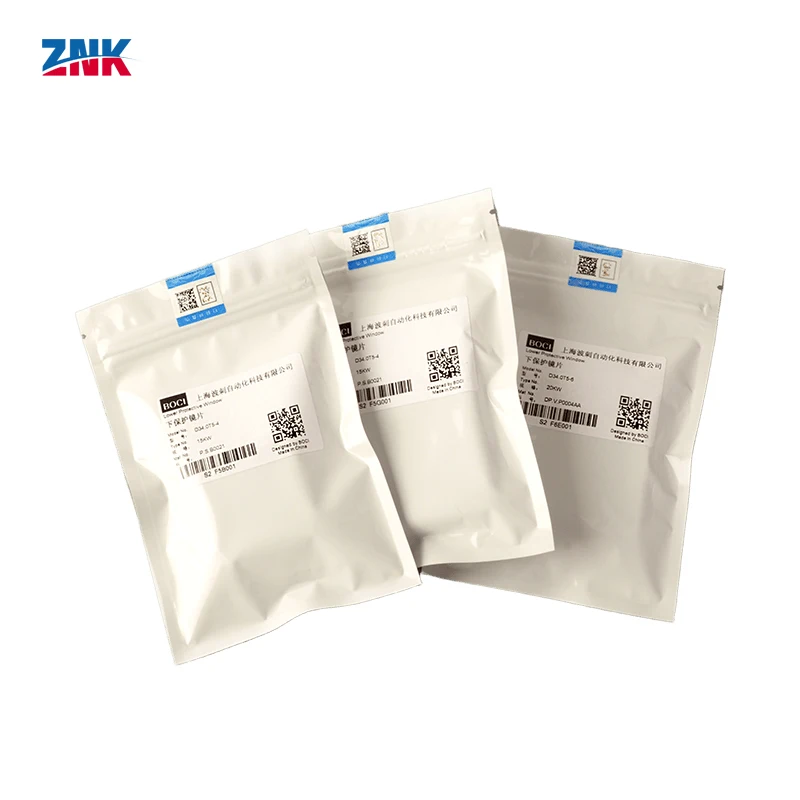
Product packaging

FAQ
1. who are we?
We are based in Anhui, China, start from 2017,sell to South America(20.00%),Eastern Europe(15.00%), Southern
Europe(12.00%),Western Europe(12.00%),Northern Europe(10.00%),North America(8.00%), Mid East(8.00%),Eastern
Asia(6.00%),Africa(5.00%),Southeast Asia(2.00%),South Asia(1.00%),Oceania(1.00%). There are total about 11-50 people in our office.
2. how can we guarantee quality?
Always a pre-production sample before mass production;
Always final Inspection before shipment;
3.what can you buy from us?
CO2 Laser Cutting Machine, Fiber Laser Cutting Machine, Fiber Laser Marking Machine, CO2 Laser Marking Machine, CNC Machines
4. why should you buy from us not from other suppliers?
Our company is a high-tech enterprise with years of experience in R&D, production, sales and technical maintenance in the laser equipment industry.With the professional laser technology,advanced technology and new design concept.
5. what services can we provide?
Accepted Delivery Terms: FOB,CFR,CIF,EXW,Express Delivery;
Accepted Payment Currency:USD,EUR,JPY,CAD,AUD,HKD,GBP,CNY,CHF;
Accepted Payment Type: T/T,L/C,D/P D/A,MoneyGram,Credit Card,PayPal,Western Union,Cash;
Language Spoken:English,Chinese,Spanish,Japanese,Portuguese,German,Arabic,French,Russian,Korean,Hindi,Italian
We Recommend
New Arrivals
New products from manufacturers at wholesale prices


