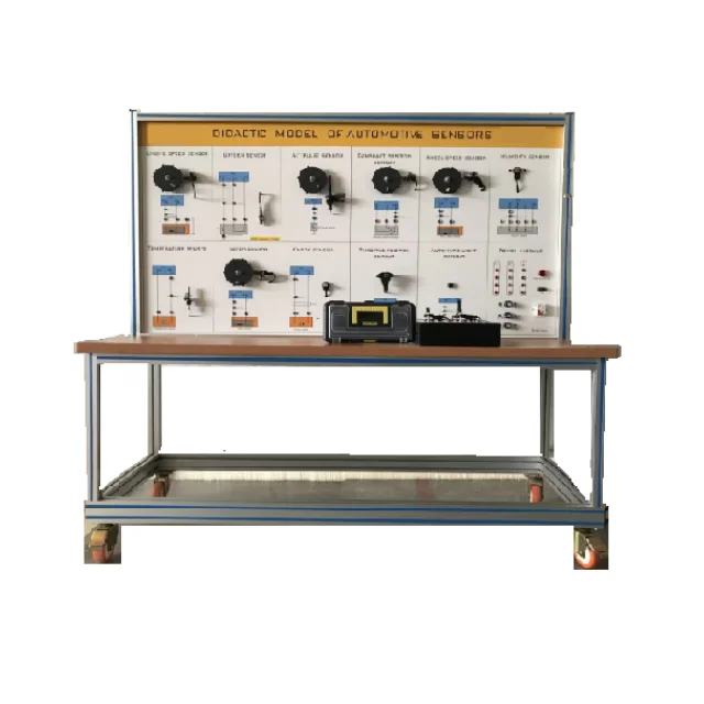
AUTOMOTIVE SENSORS DIDACTIC MODEL training panel teaching bench automobile demonstrating board car maintenance trainer
- Category: >>>
- Supplier: Shandong Hettc Intelligent Technology Co. Ltd.
Share on (1601167115657):
Product Overview
Description
1 Product Introduction
1.1 This is an automotive sensor-assisted teaching product, the product panel is arranged with more than a dozen common real automotive sensor components, and try to simulate the working state of the sensor. This test bench can enable students to understand the basic structure and working principle of automotive sensors, can understand the sensor wiring and detection, can further understand the use and function of sensors and actuators.
The product includes a test bench and an additional sensor teaching module.
There are test wires in accessory box.
1.2 The color panel is printed with the sensor wiring schematic, and the sensor detection point is configured with 4mm detection holes, so that students can connect and test and learn each sensor.
1.3 The bench panel equipped with DC 12V and DC 5V power and equipped with adjustable potentiometer (1~20Ω, 1~1KΩ, 1~10KΩ),
students can choose according to their own needs when building the circuit, and are equipped with adjustable resistance.Therefore, students can build the sensor experiment circuit independently.
1.4 The main body of the test bench adopts high-level aluminum profile structure, and four universal self-locking wheels are convenient for moving and positioning.
1.5 Power supply: single-phase AC220V/50HZ, power: <500W .
1.6 Equipment size: 1700*650*1700mm Weight: 150kg
2 Sensor principle introduction and experiment
2.1 Engine speed sensor
2.1.1 Installation location
2.1.2 Structural principle
2.1.3 Testing connection
2.1.4 Fault phenomenon
2.2 Oxygen sensor
2.2.1 Installation location
2.2.2 The role of oxygen sensor
2.2.3 Composition structure of zirconium dioxide oxygen sensor
2.2.4 Working principle of ZrO2 oxygen sensor
2.2.5 Testing connection
2.2.6 Fault phenomenon
2.3 A/T pulse sensor
2.3.1 Installation location and function
2.3.2 Testing connection
2.3.3 Fault phenomenon
2.4 Camshaft position sensor
2.4.1 Installation location and function
2.4.2 Camshaft position sensor type and structure
2.4.3 working principle
2.4.4 Testing connection
2.4.5 Fault phenomenon
2.5 Wheel speed sensor
2.5.1 wheel speed sensor installation position and function
2.5.2 Work principle
2.5.3 Testing connection
2.6 Humidity sensor
2.6.1 installation position and function
2.6.2 Sensor work principle
2.6.3 Testing connection
2.6.4 Fault phenomenon
2.7 Temperature sensor
2.7.1 Introduction to the principle of the sensor
2.7.2 Testing connection
2.7.3 Fault phenomenon
2.8 speed sensor
2.8.1 Speed sensor function
2.8.2 Structural principle
2.8.3 Testing connection
2.8.4 Fault phenomenon
2.9 Knock sensor
2.9.1 Installation position and function
2.9.2 The working principle of detonation sensor
2.9.3 Testing connection
2.9.4 Fault phenomenon
2.10 Throttle position sensor
2.10.1 Installation position and function
2.10.2 Working principle of throttle position sensor
2.10.3 Testing connection
2.10.4 Fault phenomenon
2.11 Automatic light sensor
2.11.1 Installation and function
2.11.2 Work principle
2.11.3 Testing connection
2.11.4 Fault phenomenon
2.12 PTC temperature sensor
2.12.1 Sensor Introduction
2.12.2 Work principle
2.12.3 Testing connection
2.13 Air Flow Sensor
2.13.1 Installation and function
2.13.2 work principle
2.13.3 Testing connection
2.14 Air Suction Pressure Sensor
2.14.1 Installation and function
2.14.2 working principle
2.14.3 Testing connection
2.15 Manifold Absolute Pressure Sensor
2.15.1 Installation and function
2.15.2 working principle
2.15.3 Testing connection
2.16 Electronic Accelerator Pedal Position Sensor
2.16.1 Installation and function
2.16.2 working principle
2.16.3 Testing connection
We Recommend


New Arrivals
New products from manufacturers at wholesale prices