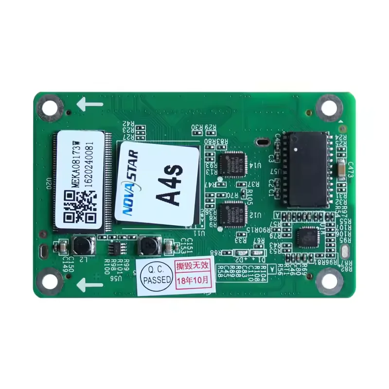
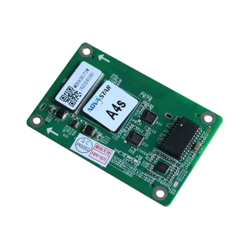
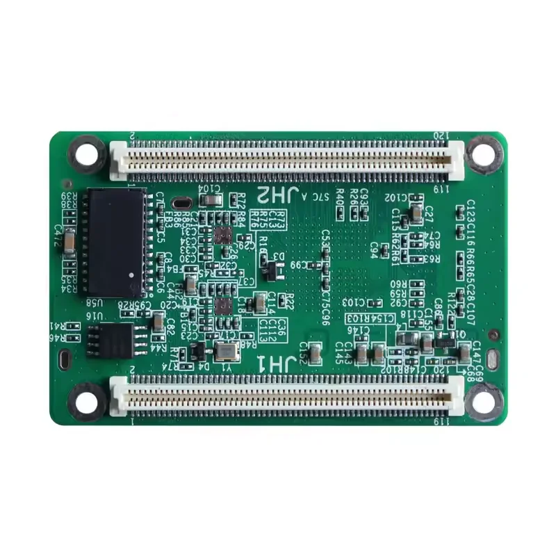
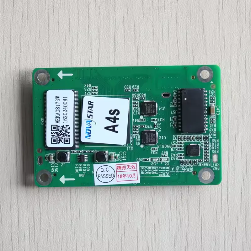
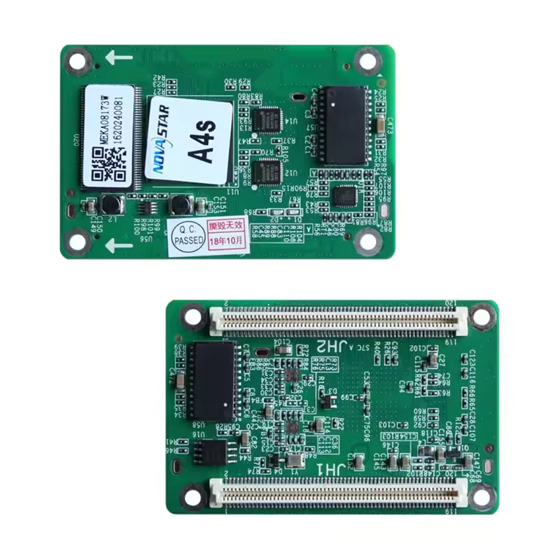
Novastar A4S LED Display Receiver Card For LED Screens
- Category: >>>
- Supplier: Shenzhen Hd Led Technology Co. Ltd.Shenzhen Ltd.
Share on (1601243331036):
Product Overview
Description
Welcome to Visit Shenzhen HD LED's Factory!
(Our Factory only 8km far from Shenzhen Bao'an International Airport)
CE.FCC.RoHS Certified
CE.FCC.RoHS Certified
16Years Factory Outlet of SMD LED Modules: Indoor P0.9-P10&Outdoor P2.5-P10
√Quality stability: Use the most advanced imported YAMAHA 40Rhigh-speed SMT machine to make SMT into LED modules
√Capacity stability: 40KK Patch Count Daily Output,SMT Machine*50,Solder Paste Printing*15, Reflow Welding Machine*10
√Full quality inspection: 1000+m2. Aging Area.72h SMD Lamp Aging Test→48h Led Module Aging Test → Pre-Installed Led Screen 48h Aging Test.Waterproof test &Vibration test


Key Features
Improvements to Display Effect
1. Pixel level brightness and chroma calibration Working with NovaLCT and NovaCLB, the receiving card supports brightness and
chroma calibration on each LED, which can effectively remove color discrepancies and greatly improve LED display brightness
and chroma consistency, allowing for better image quality.
2. Quick adjustment of dark or bright lines The dark or bright lines caused by splicing of cabinets or modules can be adjusted to
improve the visual experience. This function is easy to use and the adjustment takes effect immediately.
3. 3D function Working with the independent controller which supports 3D function, the receiving card supports 3D image output.
4. Individual Gamma adjustment for RGB Working with NovaLCT (V5.2.0 or later) and the independent controller which supports this
function, the receiving card supports individual adjustment of red Gamma, green Gamma and blue Gamma, which can effectively
control image non-uniformity under low grayscale and white balance offset, allowing for a more realistic image.
5. Image rotation in 90° increments The display image can be set to rotate in multiples of 90° (0°/ 90°/180°/270°).
Improvements to Maintainability
1. Smart module (dedicated firmware required) Working with the smart module, the receiving card supports module ID management,
storage of calibration coefficients and module parameters, monitoring of module temperature, voltage and flat cable
communication status, LED error detection, and recording of the module run time.
2. Quick uploading of calibration coefficients The calibration coefficients can be quickly uploaded to the receiving card,
improving efficiency greatly.
3. Module Flash management For modules with flash memory, the information stored in the memory can be managed. The calibration
coefficients and module ID can be stored and read back.
4. One click to apply calibration coefficients stored in module Flash For modules with flash memory, if the Ethernet cable is
disconnected, users can hold down the self-test button on the cabinet to upload the calibration coefficients in the flash
memory of the module to the receiving card.
5. Mapping function The cabinets display the receiving card number and Ethernet port information, allowing users to easily
obtain the locations and connection topology of receiving cards.
6. Setting of a pre-stored image in receiving card The image displayed on the screen during startup, or displayed when the
Ethernet cable is disconnected or there is no video signal can be customized.
7. Temperature and voltage monitoring The temperature and voltage of the receiving card can be monitored without using
peripherals.
8. Cabinet LCD The LCD module connected to the cabinet can display the temperature, voltage, single run time and total run time
of the receiving card.
9. Bit error detection The Ethernet port communication quality of the receiving card can be monitored and the number of
erroneous packets can be recorded to help troubleshoot network communication problems. NovaLCT V5.2.0 or later is required.
10. Status detection of dual power supplies When two power supplies are connected, their working status can be detected by the
receiving card.
11. Firmware program readback The firmware program of the receiving card can be read back and saved to the local computer.
NovaLCT V5.2.0 or later is required.
12. Configuration parameter readback The configuration parameters of the receiving card can be read back and saved to the local
computer.
13. LVDS transmission (dedicated firmware required) Low-voltage differential signaling (LVDS) transmission is used to reduce the
number of data cables from the hub board to module, increase the transmission distance, and improve the signal transmission
quality and electromagnetic compatibility (EMC).
Improvements to Reliability
1. Loop backup The receiving cards and the sending card form a loop via the main and backup line connections. If a fault occurs
at a location of the lines, the screen can still display the image normally.
2. Dual backup of configuration parameters The receiving card configuration parameters are stored in the application area and
factory area of the receiving card at the same time. Users usually use the configuration parameters in the application area.
If necessary, users can restore the configuration parameters in the factory area to the application area.
3. Dual backup of the application program Two copies of the application program are stored in the receiving card at the factory
to avoid the problem that the receiving card may get stuck due to program update exception.
Specifications
Indicator | Color | Status | Description |
Running indicator | Green | Flashing once every 1s | The receiving card is functioning normally. Ethernet cable connection is normal, and video source input is available. |
Flashing once every 3s | Ethernet cable connection is abnormal | ||
Flashing 3 times every 0.5s | Ethernet cable connection is normal, but no video source input is available. | ||
Flashing once every 0.2s | The receiving card failed to load the program in the application area and now is using the backup program. | ||
Flashing 8 times every 0.5s | A redundancy switchover occurred on the Ethernet port and the loop backup has taken effect. | ||
Power indicator | Red | Always on | The power input is normal. |
PRODUCTION LINE

BEST QUALITY GUARANTEED

FAQ

We Recommend

New Arrivals
New products from manufacturers at wholesale prices