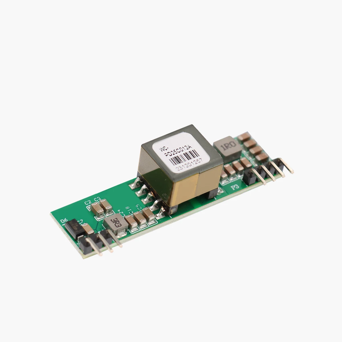
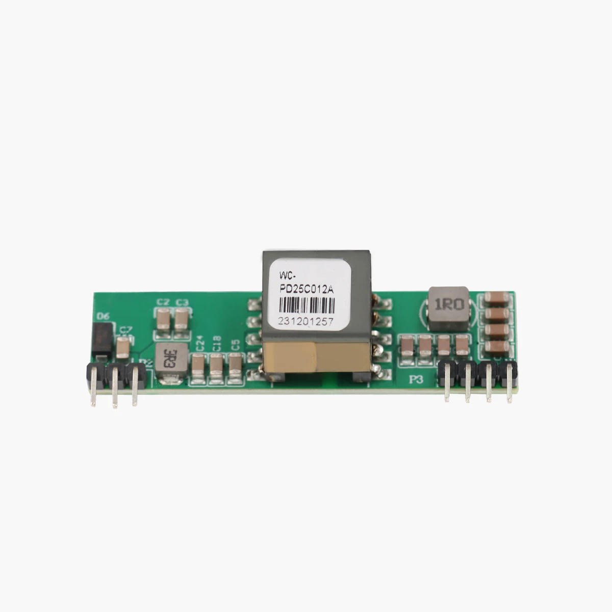
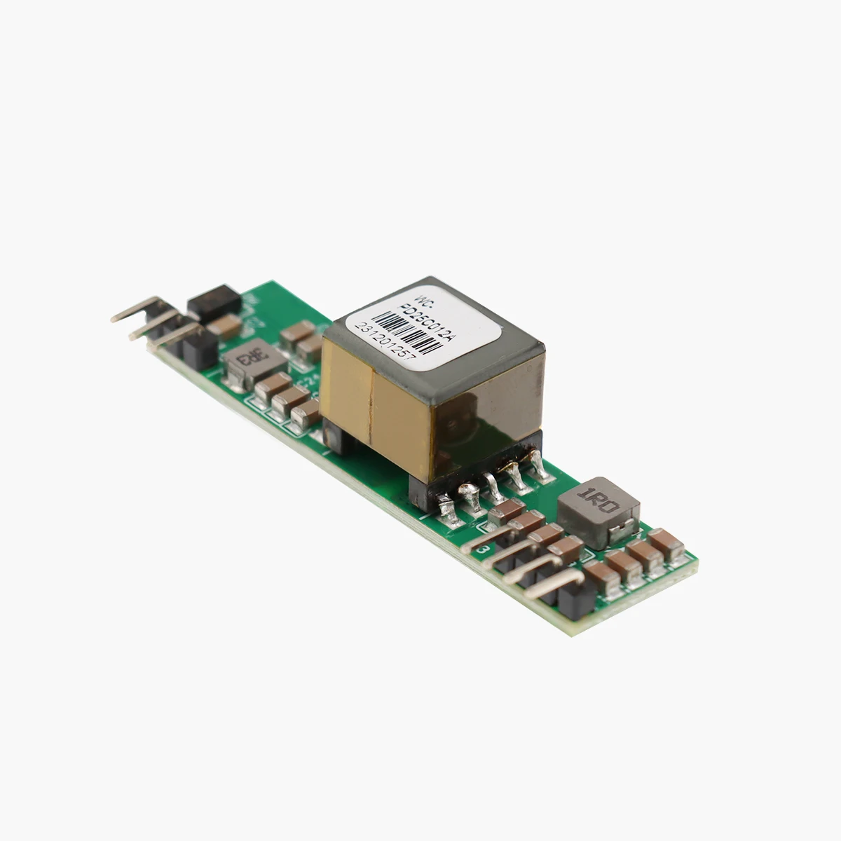
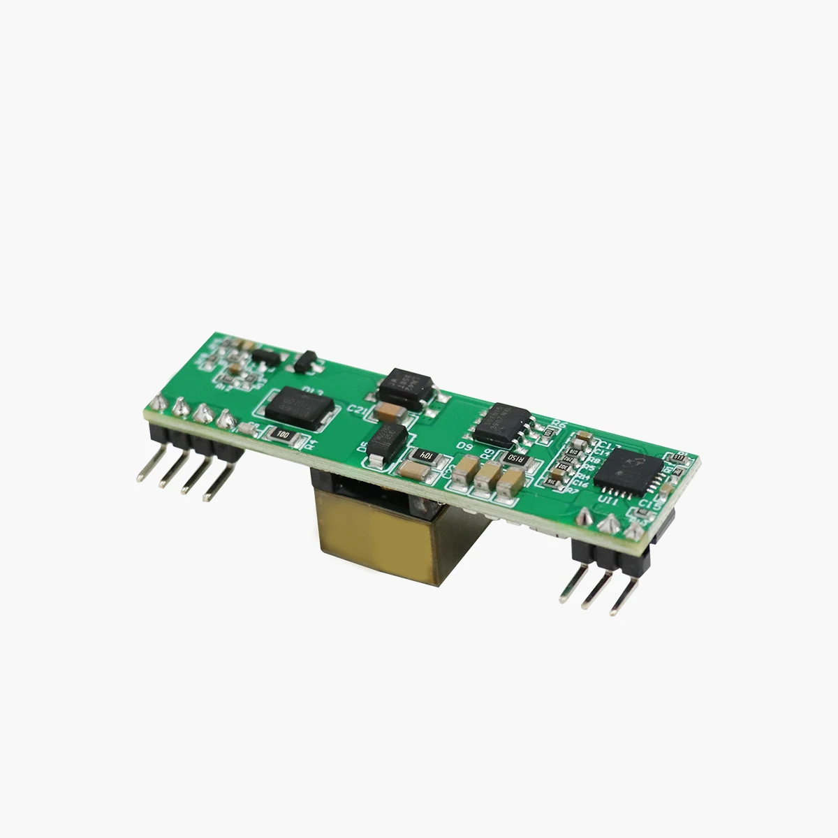
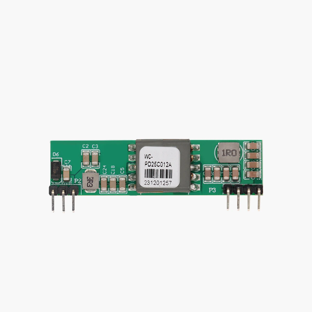
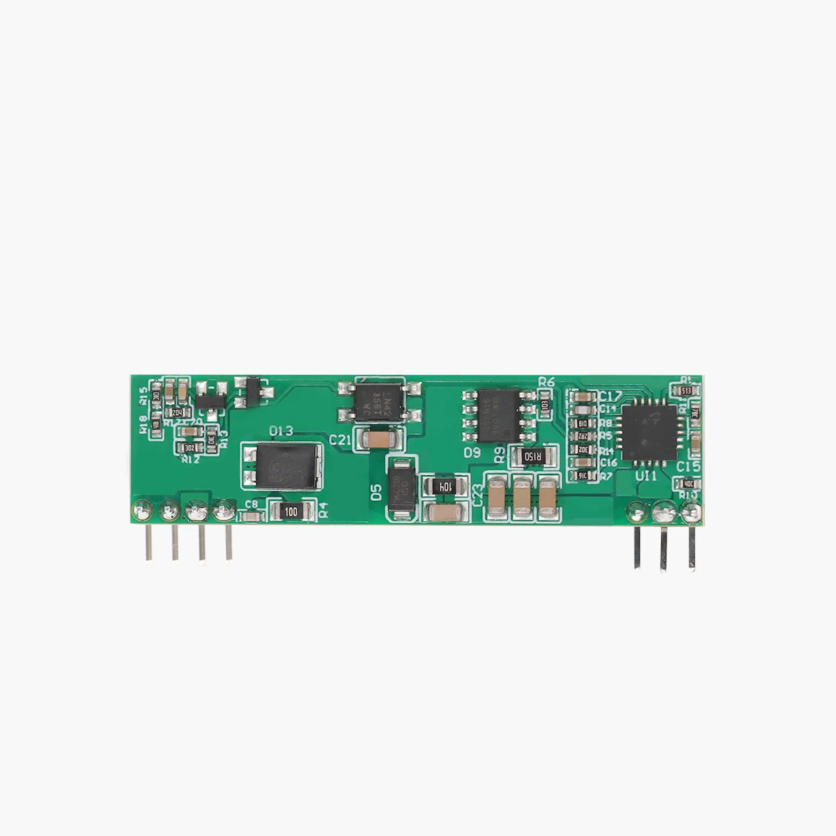
Winchen WC PD25C012A 12V 2A PoE Module IEEE802.3af/at Standard Power Module 1500V High Voltage Isolation PoE Board
- Category: >>>
- Supplier: Shenzhen Winchen Power Technology Co. Ltd.
Share on (1601275273649):
Product Overview
Description
Products Description
● Product Features
* Compliance with IEEE802.3af/at standard.
* 42V~57V wide operating voltage range.
* Maximum output power up to 24W; Rated output: 12V/2A
* The output ripple is less than 200 mV.
*Conversion efficiency can be as high as 87% (input: 48V output:12V@2A).
* It has excellent reliability and circuit protection such as over current, short circuit, under voltage and surge.
* PCBA standard size: 53.5*14*16.7mm.
* Input/Output: isolate 1500Vdc.
* Compliance with IEEE802.3af/at standard.
* 42V~57V wide operating voltage range.
* Maximum output power up to 24W; Rated output: 12V/2A
* The output ripple is less than 200 mV.
*Conversion efficiency can be as high as 87% (input: 48V output:12V@2A).
* It has excellent reliability and circuit protection such as over current, short circuit, under voltage and surge.
* PCBA standard size: 53.5*14*16.7mm.
* Input/Output: isolate 1500Vdc.
* Class 4 IEEE802.3 PD.
* High reliability: The design meets the 5 million hour average failure interval.
* High reliability: The design meets the 5 million hour average failure interval.
● Mechanical Dimensions

● Pin Definition
Pin | Name | Description |
1 | Vin+ | This pin is connected to the input negative (+) power supply using the "middle overlap method", so it needs to be connected to the center tap of the 4/5 network transformer to connect this pin. If the power supply adopts the "end crossing method", it is necessary to connect the center tap of the 1/2 network transformer to this pin |
2 | Vin- | This pin is connected to the input negative (-) power supply using the "middle overlap method", so it needs to be connected to the center tap of the 7/8 network transformer to connect this pin. If the power supply adopts the "end crossing method", it is necessary to connect the center tap of the 3/6 network transformer to this pin |
3 | NC | Reserve fixed pin |
4 | Vout- | This pin is the module output negative pole |
5 | Vout+ | This pin is the module output positive pole |
6,7 | NC | Reserve fixed pin |
● Electrical characteristics
1. Absolute maximum rating parameter
1. Absolute maximum rating parameter
No | Parameter | Symbol | Min | Max | Unit | |||||
1 | Input DC voltage | VCC | 42 | 57 | V | |||||
2 | DC Voltage Surge 1ms | VSURGE | -0.6 | 80 | V | |||||
3 | Ambient temperature | TS | -40 | 80 | ℃ | |||||
* Exceeding the above rating may cause permanent damage to the product. Functional operations under these conditions are not recommended. ● Recommended working conditions | ||||||||||
No | Parameter | Symbol | Min | Typ | Max | Unit | ||||||
1 | Input DC voltage | VIN | 42 | 48 | 57 | V | ||||||
2 | Low pressure input threshold | VLOCK | 37 | - | - | V | ||||||
3 | Ambient Temperature | TOP | -40 | 25 | 80 | ℃ | ||||||
* Applicable only to WC-PD25C012A maximum operating temperature. ● DC Characteristic | ||||||||||||
No | Parameter | Symbol | Min | Typ | Max | Unit | Test conditions | |||||||
1 | Standard Output Voltage | VDC | 11.75 | 12 | 12.2 | V | VIN=48V Tc:25℃ | |||||||
2 | Output Current(VIN=48V) | PWR | - | 2 | - | A | Wide voltage input 42-57V | |||||||
3 | Power adjustment rate | VLINE | - | 0.1 | - | % | @50% Load | |||||||
4 | Load Adjustment Rate | VLOAD | - | 1 | - | % | @VIN=48V | |||||||
5 | Ripple Output Noise | VRN | - | 200 | 250 | mVp-p | @Maximum Load | |||||||
6 | Minimum Load | RLOAD | 10 | - | - | mA | ||||||||
7 | Short circuit duration | TSC | - | - | ∞ | sec | ||||||||
8 | Efficiency (load 80%) | EFF | 82 | 87 | - | % | ||||||||
9 | Isolation Voltage (I/O) | VISO | - | - | 1500 | VPK | ||||||||
10 | Temperature Coefficient | Tc | - | 0.02 | % | Per ℃ | ||||||||
11 | Transient Rresponse | Ts | - | 100 | 250 | ms | VIN=48V VOUT=max | |||||||
* Typical number is 25℃, nominal voltage is 48V, for auxiliary design only; * Output ripple and noise can be reduced by an external filter, see the application instructions; * If operated under the specified minimum load, the module will emit sound noise, which may cause repeated hiccups in the PSE. | ||||||||||||||
● Functional Description
1. Input:
* The input terminal of WC-PD25C012A is not preset with "bridge reactor", so it is necessary to pay attention to the polarity of power supply core.
1. Input:
* The input terminal of WC-PD25C012A is not preset with "bridge reactor", so it is necessary to pay attention to the polarity of power supply core.

2. PD Power Supply Agreement
* When the module is connected to the cable, it will automatically provide the Power Device (PD) signature to the PSE when needed. The PSE recognizes that the PD is connected to that line and provides power.
* When the module is connected to the cable, it will automatically provide the Power Device (PD) signature to the PSE when needed. The PSE recognizes that the PD is connected to that line and provides power.

3. Power Classification:
* WC-PD25C012A uses IEEE802.3at(backward compatible with AF) standard and runs with Class 4 (24W) power rating by default.
Define criteria | Cable requirements | Grading parameters | Power Supply Characteristics |
IEEE802.3at (PoE Plus) | CAT5 cable or CAT6 cable | Maximum power required for Class4 devices is 13W~25.5W | 1. The DC voltage ranges from 42 to 57V, with a typical value of 48V. 2. Typical operating current is 10~600mA; typical output power: 25.5W. 3. Class4 rating supported by electrical equipment. |
IEEE802.3af (PoE) | CAT5 cable | Maximum power required for Class0 devices is 0~12.95W | 1. The DC voltage ranges from 38 to 57V, with a typical value of 48V. 2. Typical operating current is 10~350mA; typical output power: 15.4W; 3. The overload detection current is 350~500mA. 4. Provide 4 Class Power Requests for PD Devices ranging from 3.84 to 12.95W |
The maximum power required for Class1 devices is 0~3.84W | |||
The maximum power required for Class2 devices is 3.85W~6.49W | |||
The maximum power required for Class3 devices is 6.5W~12.95W |
● Typical Connection Diagram


Welcome to customize POE modules with various sizes and appearance functions.
According to the requirements of the drawing board, research and development fees will be charged in the early stage. After ordering a certain number of modules (usually 1000 pieces), the research and development fees can be deducted from the payment. Wait until the samples are qualified before mass production.
According to the requirements of the drawing board, research and development fees will be charged in the early stage. After ordering a certain number of modules (usually 1000 pieces), the research and development fees can be deducted from the payment. Wait until the samples are qualified before mass production.


We Recommend
New Arrivals
New products from manufacturers at wholesale prices