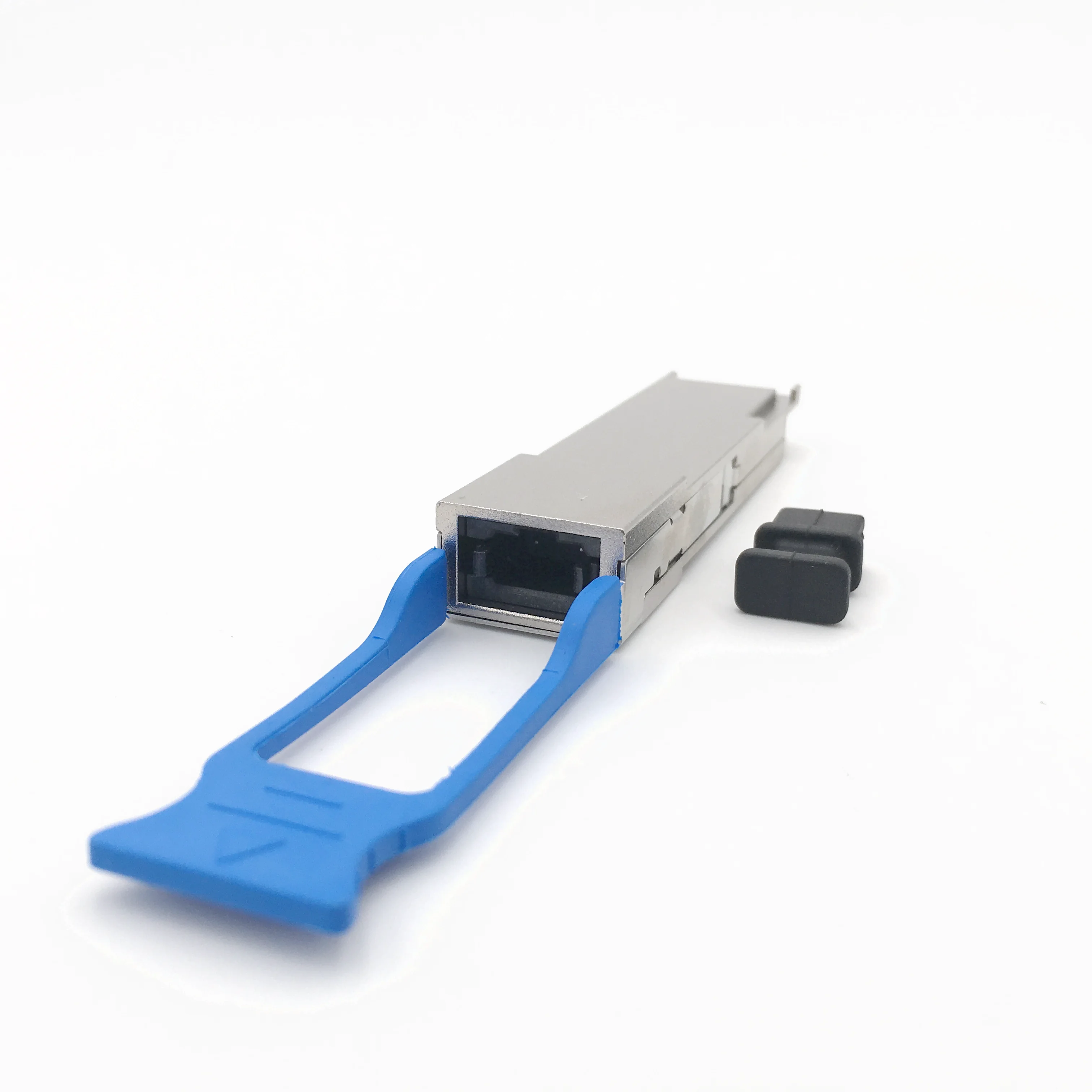
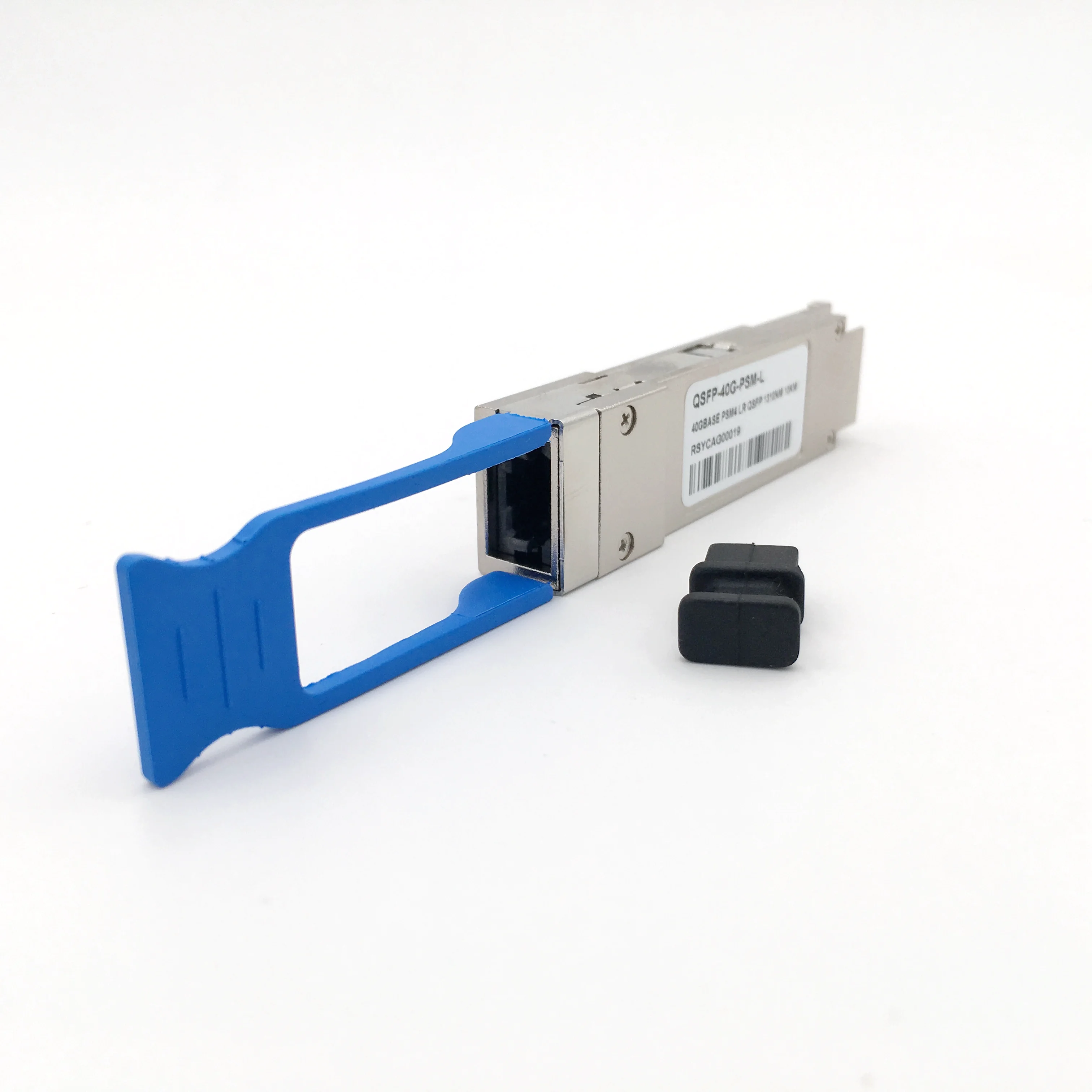
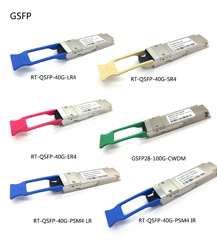
SFP Module QSFP fiber optic transceiver 40G 10KM 20km 40kmoptical module
- Category: >>>
- Supplier: Wuhan Wolon Communication Technology Co. Ltd.Wuhan Ltd.
Share on (1601322200731):
Product Overview
Description
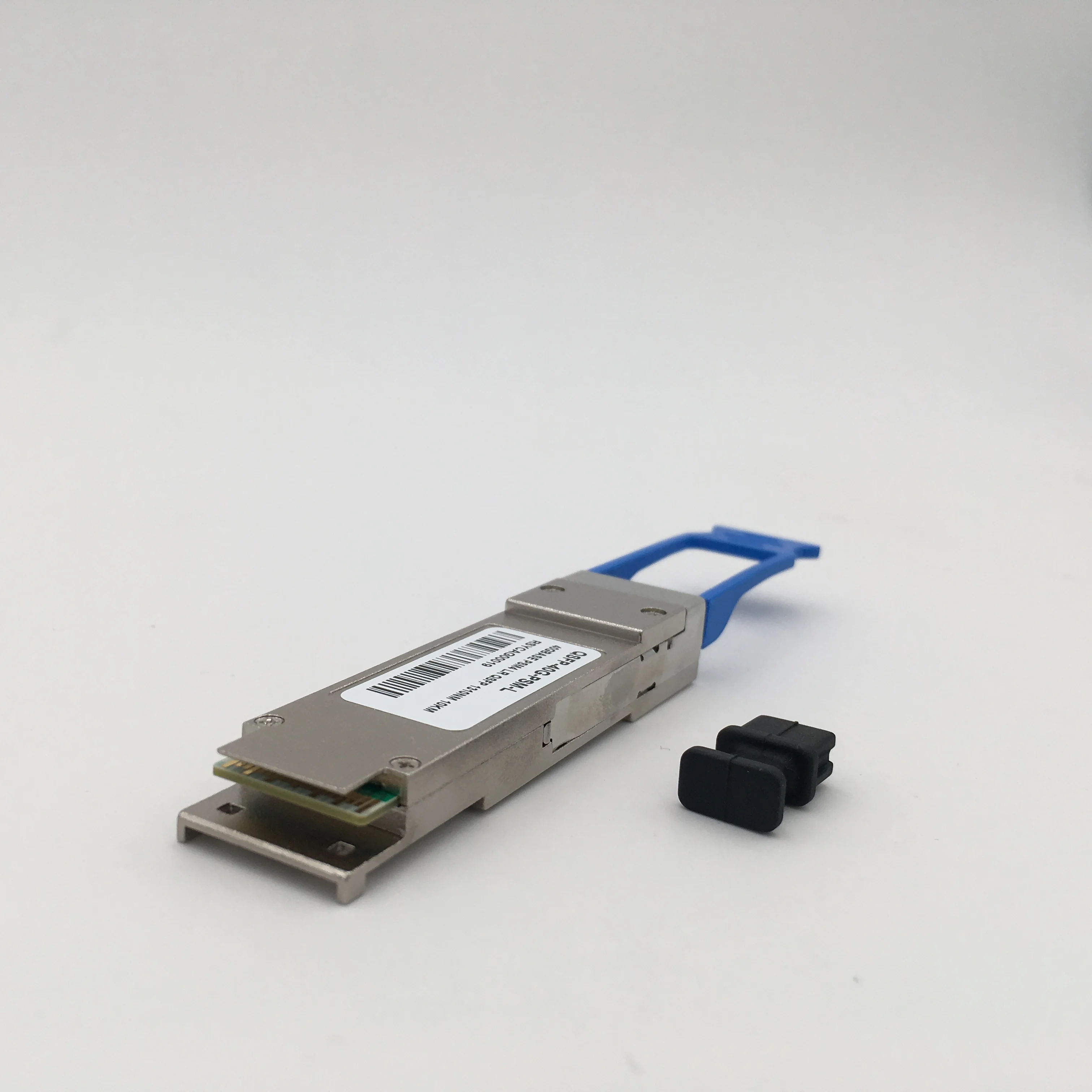
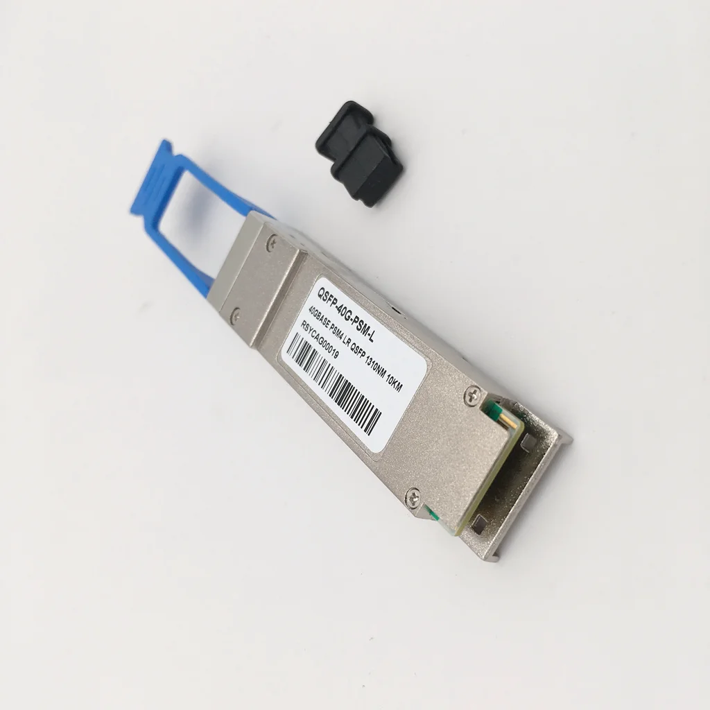
factory supply QSFP+ fiber optic transceiver 40G 10KM optical module
Product Description
40Gb/s QSFP+ PSM4 10KM is a Four-Channel, Pluggable, Parallel, Fiber-Optic QSFP+ Transceiver for InfiniBand QDR/DDR/SDR, 10G/8G/4G/2G fiber channel, PCIe and SAS Applications. The QSFP full-duplex optical module offers 4 independent transmit and receive channels, each capable of 10.3Gbps operation for an aggregate data rate of 40Gbps 10km using single mode fiber. These modules are designed to operate over single mode fiber systems using 1310nm DFB laser array. An optical fiber ribbon cable with an MPO/MTPTM connector can be plugged into the QSFP module receptacle. QSFP+ PSM LR4 is one kind of parallel transceiver which provides increased port density and total system cost savings.
Key Feature
Parameter | Symbol | Min | Typical | Max | Unit | Notes | |
Transmitter | |||||||
Center Wavelength | λC | 1270 | 1310 | 1350 | nm | 1 | |
RMS Spectral Width | λrms |
|
| 3.5 | nm | 1 | |
Average Launch Power, each lane | PAVG | -5.5 | -0.5 | +2.3 | dBm |
| |
Optical Modulation Amplitude (OMA) | POMA | -4.5 | -0.5 | +3.5 | dBm | 1 | |
Difference in Launch Power between any two lanes | Ptx,diff |
|
| 5.0 | dB |
| |
Launch Power in OMA minus Transmitter and Dispersion Penalty (TDP), each Lane | OMA-TDP | -9.7 |
|
| dBm | 1 | |
Rise/Fall Time | Tr/Tf |
|
| 50 | ps |
| |
Extinction Ratio | ER | 3.5 |
|
| dB |
| |
Relative Intensity Noise | Rin |
|
| -128 | dB/Hz |
| |
Optical Return Loss Tolerance | TOL |
|
| 12 | dB |
| |
Transmitter Reflectance | RT |
|
| -12 | dB |
| |
Transmitter Eye Mask Margin | EMM | 10 |
|
| % | 2 | |
Transmitter Eye Mask Definition {X1, X2, X3, Y1, Y2, Y3} |
| {0.25, 0.4, 0.45, 0.25, 0.28, 0.4} |
|
| |||
Average Launch Power OFF Transmitter, each Lane | Poff |
|
| -30 | dBm |
| |
Receiver | |||||||
Center Wavelength | λC | 1270 | 1310 | 1350 | nm |
| |
Damage Threshold | THd | +3 |
|
| dBm |
| |
Overload, each lane | OVL | +1 |
|
| dBm |
| |
Receiver Sensitivity in OMA, each Lane | SEN |
|
| -12.5 | dBm |
| |
Difference in Receive Power between any two Lanes (OMA) | Prx,diff |
|
| 5.0 | dB |
| |
Signal Loss Assert Threshold | LOSA | -30 |
|
| dBm |
| |
Signal Loss Deassert Threshold | LOSD |
|
| -15 | dBm |
| |
LOS Hysteresis | LOSH | 0.5 |
| 6 | dB |
| |
Optical Return Loss | ORL |
|
| -12 | dBm |
| |
Receive Electrical 3 dB upper Cutoff Frequency, each Lane | Fc |
|
| 12 | GHz |
| |
Notes:
1. Transmitter wavelength, RMS spectral width and power need to meet the OMA minus TDP specs to guarantee link performance.
2. The eye diagram is tested with 1000 waveform.
Product Show


Exhibition:

We Recommend

New Arrivals
New products from manufacturers at wholesale prices