
MDA CGA EGA RGB to VGA Converter GBS8219 for Mazak Fanuc machine
- Category: >>>
- Supplier: Shenzhen Gonbes Technology Co. Limited
Share on (2009101222):
Product Overview
Description
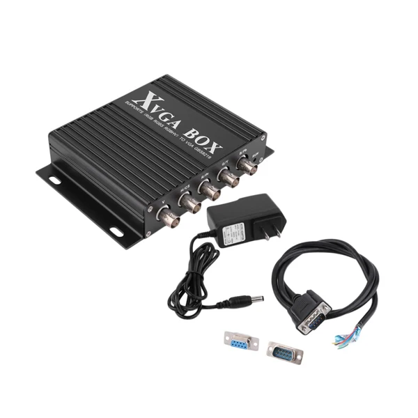
CNC industrial MDA / CGA / EGA / RGB TO VGA Converter GBS8219 for Mazak, Heidenhain machine
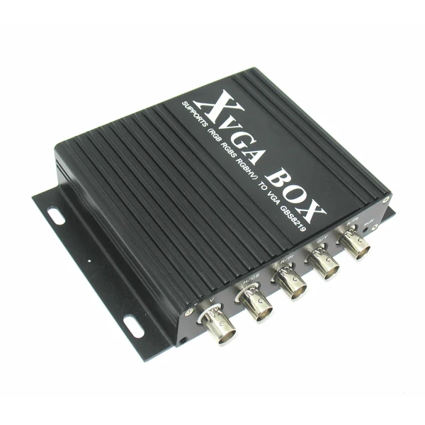
Based on the GBS 8218(XRGB BOX), newly released XVGA BOX(GBS8219) can achieve full automatic conversion from MDA / CGA / EGA / RGB…to VGA industrial video signal. It's widely used for various kinds of FHKD, such as Digital Control Machine Tool Display, DCS Display, injection molding machine, analytical instrument, Specialized Display of navigation and import production line, armamentarium, Specialized Display of airport, railway and financial facility, Special size Display,
USAGE: repairing & replacing CNC / Industrial CRT monitor, like Fanuc, Siemens, Mazak, Heidenhain, Hitachi, Toshiba, Mitsubishi, Sharp, Tatung, Totoku, and Magnetek, and etc.
Mitsubishi Model |
C-3270LP |
C-3470 |
C-3470J |
C-5470Ns |
C-5470YE |
CDT14111B |
CDT14148B |
MDT947 |
MDT947B |
MDT947B-1A |
MDT947B-2B |
MDT962B-1A |
MDT1283B |
MDT1283B-1B |
Special size display:
Input | Signals | MDA,CGA,EGA,RGB,RGB Sog,RGBS,RGBHV,YPbPr |
Interface | 5BNC, 9pin,3pin,6pin,14pin,20pin,25pin | |
Horizontal Frequency Rate(H) | 12kHz to 40kHz automatically recognized | |
Output | Supports | D-15pin standard VGA/SVGA,Resolution:800*600/60HZ, 640*480/60hz |
Interface | D-Sub 15 PIN standard VGA port | |
Power | DC 12V 1.0A | |
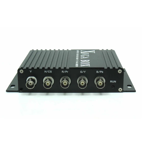
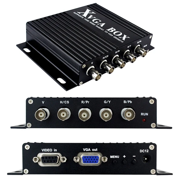
Definition for I/O interface:
Item | Spec. | Remarks |
V | To connect V interface of the input device | Input Channel I |
H/CS | To connect H(CS) interface of the input device | |
R/Pr | Red signal input/ Pr signal input | |
G/Y | Green signal input/ YPBPR -Y signal input | |
B/Pb | Blue Signal input/YPBPR -Pb signal input | |
RUN | Running Status Indicator |
|
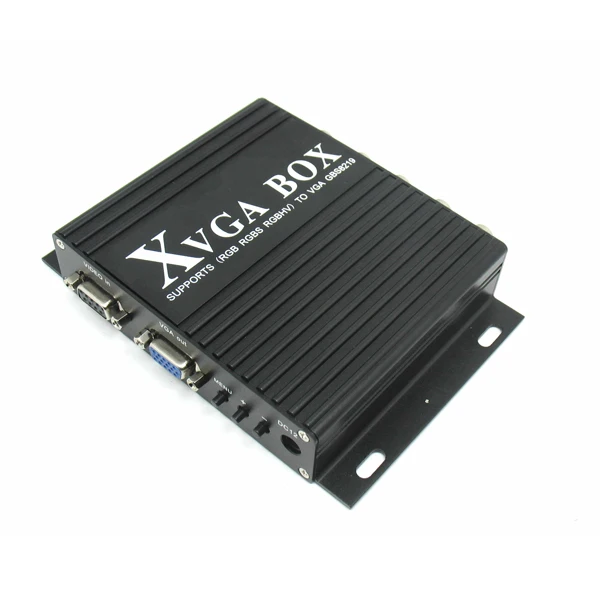
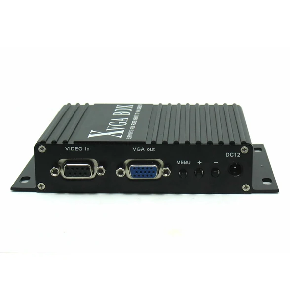
VIDEO in | To connect 9-pin interface of the input device | Input Channel II |
VGA out | Standardsub-15p VGA female interface | VGA Output |
MENU | Use to adjustscreen /programming |
|
DC12 | Power inputDC12V, 1A |
|
Table 4.1 Definition for Input Channel II:
| PIN | InputSignal |
p1(GND) | Connect to the ground |
p2(GND) | Connect to the ground |
P3(R) | connect R(ed) interface of the input device |
P4(G) | connect G(reen) interface of the input device |
P5(B) | connect B(lue) interface of the input device |
P6 | Undefined(null) |
P7 | Undefined(null) |
P8(H) | connect H(CS) interface of the input device |
P9(V) | connect V interface of the input device |
Figure 4.1 Definition for Input Channel II
Table 4.2 Definition for Input Channel I
BNC | Input Signal | Connection image |
Pb,Y,Pr | YPbPr input signal (right image) Interface: three BNC slot, connected to the corresponding Pb, Y, Pr interface, then Y monochrome port. |
Figure 4.2 Analog 3BNC (YPBPR) Input. |
R,G,B | RGB Sog input signal (right image) Interface: three BNC slot, connected to the corresponding R, G, B slot, then G monochrome port. |
Figure 4.3 Analog 3BNC (RGB Sog) Input. |
R,G,B,S | RGBS CS Composite Sync (right image) Interfaces: 4 BNC slot, connected to the corresponding R, G, B, S I, monochrome then G, S I |
Figure 4.4 Analog 4BNC (RGBS CS) Input. |
R,G,B,H,V | RGBHV separate sync (right image) Interface: 5 BNC port, connected to the corresponding R, G, B, H, V I, monochrome then G, H, V I |
Figure 4.5 Analog 5BNC (RGBHV) Input. |


We Recommend


New Arrivals
New products from manufacturers at wholesale prices


