
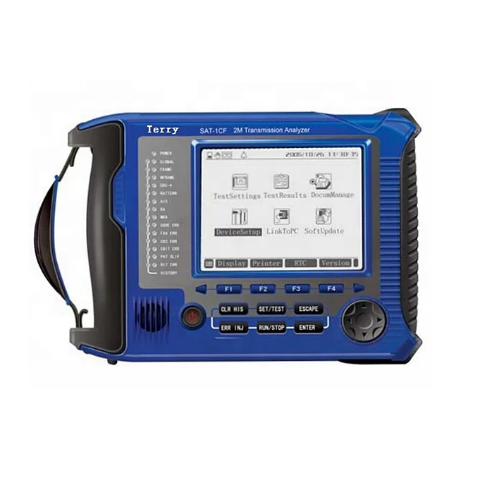
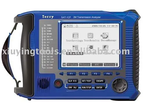
2M Optical Bit Error Rate Tester Transmission Analyzer
- Category: >>>
- Supplier: Zhangjiagang Jinfeng Hardware Tools Co. Ltd.
Share on (287062227):
Product Overview
Description
Major Functions
For 2Mbit/s:
Service-interrupted error
Online error testing
Framed and unframed signals generating and receiving
2Mbit/s unframed error performance testing
2Mbit/s framed N×64kbit/s channel error testing
Bit error, coding error, frame error, CRC error and E bit error testing
Signal loss alarm, AIS alarm, framed remote alarm, multi-framed remote alarm, out-of-frame, and pattern loss alarm
Frequency offset testing
Line signal level and frequency testing
Voice channel signal level and frequency testing
Pattern slip testing
Clock slip testing
Straightforward signaling
Audio frequency testing
Loop circuit delay testing
Automatic protection switching time testing (APS)
Clock bias function
Sound monitoring
Duplex 2Mbit/s detecting and monitoring
Signal state display. Voice channel content display. Voice channel busy indication
Alarm and error histogram analysis
Time slot content analysis, drop and insert signal on each time slot
Framed content analysis
G.703 Template analysis
G. 821/G. 826/M. 2100 error analysis
Multi error and alarm inserting
Three input modes (terminating, bridging and monitoring)
Three clock options (internal, external and picking-up)
Jitter testing function
Touch screen TFT color LCD (optional)
* The functions of yellow fonts description is a module for user to select.
For Datacom:
V.24/RS232/V.28, V.35, V.36, X.21, RS-449, RS-485, RS422, EIA-530, EIA-530A datacom testing
SYNCH and ASYNCH testing
DTE and DCE emulation
Bit code testing
Pattern slip testing
Signal loss alarm
Line signal level and frequency testing
Loop delay testing
Automatic protection switching time testing(APS)
G.821, M2100 service interrupt error testing
For co-directional 64Kbit/s:
Service interrupt error testing
Bit code testing
Pattern slip testing
Signal loss, AIS alarm
Line signal frequency testing
Loop delay testing
Automatic protection switching time testing(APS)
G.821, M.2100 error testing
Technical Index
· 2Mbit/s Technical Index
(1) Signal input rate: 2048kbit/s ± 100ppm (G.703 requirement±50PPM)
(2) Signal code: HDB3, AMI.
(3) Input jitter tolerance: Up to the requirement of Figure 10.1.
Fig.10.1 Input Jitter Tolerance
(4) Input balance response: attenuation complies with the law of square root of frequency, and is within the range of 0 to 6dB at 1024 kHz.
(5) Input Impedance
(5.1) Unbalance terminating: 75W
Balance terminating: 120W
Reflection loss >18dB within 50Hz~3100kHz
(5.2) Unbalance bridging: >750W
Balance bridging: >1200W
(5.3) Unbalance monitoring: 75W, 26dB gain
Balance monitoring: 120W, 26dB gain
Reflection loss >18dB within 50Hz~3100kHz
(6) Signal structure
(6.1) Unframed structure
(6.2) Framed structure: PCM30, PCM31, PCM30CRC, PCM31CRC
Framed structure complies with the requirement of G. 704
(7) Testing pattern: 26-1, 29-1, 211-1, 215-1, 220-1, 223-1, and artificial code
(8) Impedance of output interface:
(8.1) Unbalance 75W, up to G. 703
(8.2) Balance 120W, up to G. 703
(9) External clock input
(9.1) Signal form: HDB3, NRZ
(9.2) Balance terminating resistance: 120W
Unbalance terminating resistance: 75W
Balance bridging resistance: >1200W
Unbalance bridging resistance: >750W
(10) Error code insertion: None, single, or ratio 10-1~10-7.
· Co-directional 64k Technical Index
(1) Signal input rate: 64kbit/s ± 100ppm(G.703 requirement±100PPM)
(2) Input impedance: Balance 120W, up to G.703
(3) Input jitter tolerance: Up to G.823.
(4) Impedance of output interface: Balance 120W, up to G.703
(5) Testing pattern: 26-1, 29-1, 211-1, 215-1, 220-1, 223-1, and artificial code
· Datacom Index
(1) Data interface type: V.24, V.35, V.36, X.21, RS-449, RS-485, EIA-530 and EIA-530A.
(2) Generator
(2.1) SYNCH mode
Clock source: Internal or external clock
Phase relation between clock and data: co-direction or reverse direction.
Rate: 1.2, 2.4, 4.8, 9.6, 14.4, 19.2, 38.4, 48, 56(kbps), N×64kbps (N=1~32)
Error: ±15ppm (ppm: parts per million)
(2.2) ASYNCH mode
Rate: 50,75,110,150,200,300,600,1200,2400,3600,4800,7200,9600; 14.4k,19.2k,38.4k,57.6k(bps)
Data structure: Word length: 5, 6, 7, 8(bits) Stop bit: 1, 2(bits)
Odd-even check: odd, even, 1, 0, none
(2.3) Error code insertion: None, single, or ratio 10-1~10-7.
(3) Receiver
(3.1) SYNCH mode
Clock source: Internal or external clock
Phase relation between receive clock and receive data: Equidirection or reverse direction.
Clock Rate: 2048kbps at a maximum
(3.2) ASYNCH mode
The rate and data are the same as those of the generator.
(4) Testing pattern: 26-1, 29-1, 211-1, 215-1, 220-1, 223-1, and artificial code
Other Parameters
· Power supply
(1) Special power adapter
Input: AC220V 50Hz
Output: DC 9V 1A
(2) Internal rechargeable battery
4000mAh, 6V nickel-hydrogen rechargeable battery
Working time: 8 hours
Charging: 8 hours at power-off state, and 12 hours at power-on state
· Dimension and weight
L×W×H: 200×160×42mm
Weight: 950g
· Ambient parameters
Operation temperature: -10~50
Storage Temperature: -30~+70
Humidity: 5%~90%, non-condensing
Standard Configuration

We Recommend


New Arrivals
New products from manufacturers at wholesale prices


