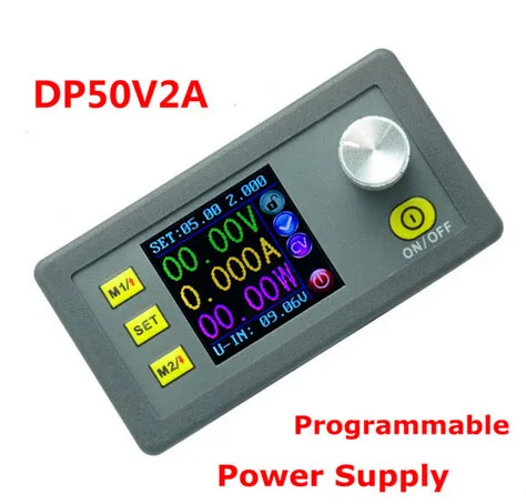
DP50V2A Constant Voltage current Step down Programmable Power Supply module buck Voltage regulator converter color LCD
- Category: >>>
- Supplier: Shenzhen Zvepower Technology Co. Ltd.
Share on (60512742671):
Product Overview
Description
start16363955656717
All our products are devised and produced by ourselves. So believe that our quality, price and service will definitely give you satisfaction!
Programmable Control Supply Power Module
Product model: DP50V2A
1. General Information
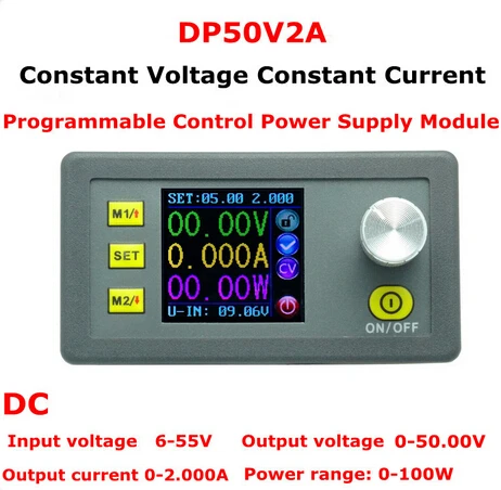
The constant voltage and constant current programmable control power supply module put the collection of analog integration and digital control functions in one. Its adjustable output voltage range is 0-50.00V, step by 0.01V. Its adjustable output current range is 0-2.000A, step by 0.001A. This module has power-down stored function and can store 10 groups preset value. And it also has the function of extracting quickly two groups stored value. Compared with the traditional analog power supply, it is more convenient to quickly extract the voltage or current required. LCD display on the module has the function digital voltmeter and ammeter. You can view the preset voltage, input voltage, output voltage, the preset current, output current, output power, etc. on the output state remind area, you can see that output opens or not, the state of constant voltage and constant current, output is normal or not, the key is locked or not, and the current data groups that is being used. On the setting data interface, you can adjust overvoltage value, overcurrent value, over-power value, data set and LCD brightness. This module has an intelligent long-life ball bearing fan. When the output current is more than 0.5A, the fan will start working automatically to help product cooling to ensure output big power. This module has many advantages, small size, advanced function, good visual effect, high operability, high-precision, being used independently, being inset into the device and been widely applied.
2. Technical parameters
Input voltage range: 6-55V Output voltage range: 0V-50.00V
Output current: 0-2.000A Output power range: 0-100W
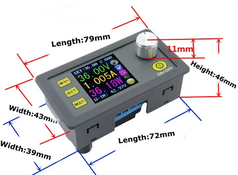
Product Weight: 85g Product Dimension: 79*43*48(mm) (L*W*H)
Open size: 71mm*39mm Output voltage resolution: 0.01V
Output current resolution: 0.001A Output Voltage accuracy: ± (0.5% + 1 digits)
Output Current accuracy: ± (0.5% + 2 digit)
Note: On the status of output, Inputs must be 1 V higher than the output. When the output current value is higher than 0.5A, the cooling fan begins to work.
The correlaion table of DP series (DP20V2A, DP30V3A ,DP50V2A , DP50V5A and DP30V5A (Simple LED version DP30V5AL )) and DPS series(DPS3003,DPS3005,DPS5005,DPS3012, DPS5015)
If you want to see DP20V2A click this
If you want to see DP30V3A click this
If you want to see DP50V2A click this
If you want to see DP50V5A click this
If you want to see DP30V5A click this
If you want to see DP30V5A-L click this
If you want to see DPS3003 click this
If you want to see DP3005 click this
If you want to see DP5005 click this
If you want to see DP3012 click this
If you want to see DP5015 click this
Difference between DP and DPS | DPS series are updated version. Panel is different. In DPS series, we change the M1/↑and M2/↓ into V/↑and A/↓. You can press those button set the voltage and current fast. We add a new function "set default boot open or close output" Others are not changed.. DPS5005 still need diode to charge the battery. | |||||||||
Input voltage | 4.5-23V | 6-35V | 6-55V | 6-55V | 6-40V | 6-40V | 6-40V | 6-55V | 6-40V | 6-60V |
Output voltage | 0-20.0V | 0-32.0V | 0-50.00V | 0-50.00V | 0.00-32.00V | 0.00-32.00V | 0.00-32.00V | 0.00-50.00V | 0.00-32.00V | 0.00-50.00V |
Output current | 0-2.00A | 0-3.10A | 0-2.000A | 0-5.000A | 0-5.000A | 0-3.000A | 0-5.000A | 0-5.000A | 0-12.00A | 0-15.00A |
Output power | 0-40W | 0-99W | 0-100W | 0-250W | 0.00-160.0W | 0-96W | 0-160W | 0-250W | 0-384W | 0-750W |
Voltage resolution | 0.1V | 0.1V | 0.01V | 0.01V | 0.01V | 0.01V | 0.01V | 0.01V | 0.01V | 0.01V |
Current resolution | 0.01A | 0.01A | 0.001A | 0.001A | 0.001A | 0.001A | 0.001A | 0.001A | 0.01A | 0.01A |
Product size | 79*34*26mm | 79*34*26mm | 79*34*48mm | 79*34*48mm | 79*34*48mm | 79*43*41mm | 79*43*48mm | 79*43*48mm | 79*43*48mm (display ) 93*71*41(power) | 79*43*48mm (display ) 93*71*41(power) |
screen | LCD | LCD | Color LCD | Color LCD | Color LCD | Color LCD | Color LCD | Color LCD | Color LCD | Color LCD |
Fan | NO (don't need) | YES | YES | NO(don't need) | NO(don't need) | NO(don't need) | NO (don't need) | NO (don't need) | YES | YES |
Charge the battery | NO | NO | NO | Yes(but need a diode) | YES | yes | yes | Yes(but need a diode, it will be with module) | yes | Yes |
Function | Preset output voltage / current Power down storage Store shortcut storage value Exact shortcut storage value Adjust LCD brightness Open or close output 2 data groups Preset output voltage / current Power down storage Store shortcut storage value Exact shortcut storage value Adjust LCD brightness Open or close output 2 data groups | Preset output voltage / current(in two places by SET KEY) Preset protection value 6 running status icons Key lock Data setting and store the specified data group Store shortcut storage value Exact shortcut M1 or M2 or specified data group Adjust LCD brightness Open or close output 10 data groups
| Preset output voltage / current(in two places, by V,A button and SET KEY) Preset protection value 6 running status icons Key lock Data setting and store the specified data group Store shortcut storage value Exact shortcut M1 or M2 or specified data group Adjust LCD brightness Open or close output 10 data groups Set default boot open or close output | |||||||
3. Connection description
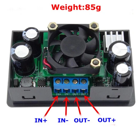
IN+: Input positive IN-: Input negative:
OUT+: Output positive: OUT-: Output negative
Note: Input voltage range is 6-55V and 55v is the limit voltage; please leave a room to use. Or else it will be burnt. The input must be DC-DC, not AC 220V, or else it will be burnt too. Though this module has reverse connection protection and output short circuit protection, you can muse be in strict accordance with connection description to connect. If you connect the supply power with output, the module will be burnt.
4. Panel and Display interface description


5. Operating instructions
When connect the power supply, the screen shows welcome window firstly and then comes into main interface. On the main interface, the output set voltage value and the output set current value is on the top of the screen. The big font value on the left are the current real output voltage, the current real output current and the current real output power. Input voltage is on the bottom of the screen. There are some running status icons on the right of the screen, key lock icon, abnormal output status icon, constant voltage and constant current icon, data set tip icon and opening or closing output icon.
5.1 Set the output voltage and output current on the main interface.
On main interface, press SET key shortly, you can enter into data setting status. Then press the coding potentiometer, and then enter to adjust the numerical value. Press coding potentiometer to enter into the status of adjusting the numerical value you want to adjust. Turn coding potentiometer to adjust the numerical value. Turn by clockwise rotation to increase the numerical value; Turn by counterclockwise to decrease the numerical value. If you want to exit adjusting the numerical value, press shortly SET. In the same time the preset value will be stored. Or you can do nothing in one minute, the status will be automatically existed and the preset will be stored too.
- Set the data on the data setting interface
On the main interface, you can press SET key twice to enter into data setting interface.
(1) Set the output voltage and output current on the data setting interface. On the data setting interface, press shortly M1/↑or M2/↓ to page up or page down to U-SET or I-SET, and then press shortly the coding potentiometer to enter into the status of adjusting the numerical value you want to adjust. Turn codding potentiometer to adjust the numerical value. If you want to exit adjusting the numerical value, press shortly SET key.
(2) Set the protection value. On the data setting interface, press shortly M1/↑or M2/↓ to page up or page down to S-OVP, S-OCP or S-OPP and then press shortly the codding potentiometer to enter into the status of adjusting the numerical value you want to adjust. Turn coding potentiometer to adjust the numerical value. If you want to exit adjusting the numerical value, press shortly SET key.
(3) Adjust the brightness of screen. On the data setting interface, press shortly M1/↑or M2/↓ to page up or page down to B-LED, and then press shortly the coding potentiometer to enter into the status of adjusting the brightness of screen. Turn codding potentiometer to adjust the numerical value you need. If you want to exit adjusting the numerical value, press shortly SET key. There are six brightness levels of LCD screen, 0-5 level. Rank 0 is the darkest; rank 5 is the brightest. You can choose what you like.
(4) Data setting and store the specified data group. On the data setting interface, press shortly M1/↑or M2/↓ to page up or page down to M-PRE, and then press shortly the coding potentiometer to enter into the status of choosing the data groups. Turn coding potentiometer to choose the data group you need to view. Then the data group you need will be displayed. And then press the coding potentiometer to enter into status of changing output state. Turn coding potentiometer to choose ON or OFF. When choose ON, the data group is extracted and the output status remain the same. When choose OFF, the data group is extracted and the output is closed. If you want to exit choosing data set, press shortly SET key. Then press shortly M1/↑or M2/↓ to page up or page down to other place to adjust the data you need. After data setting done, keep pressing SET key more than 2s, all the data you set are automatically stored into the specified data group. In the same time, you can see the group number on the right of screen. At last you can press shortly SET key back to the main interface.
6. Function description.
6.1 Open or close the output. You can press ON/OFF key to open or close the output on any interface.
6.2 Lock the button to avoid wrong operation.
On the any interface, you can keep pressing coding potentiometer more than 2s, all buttons are locked. You can see the key lock icon on the right of screen. If you want to unlock all buttons, keep pressing codding potentiometer more than 2s, all buttons are unlocked. The key unlock icon will be display on the right of screen.
6.3 M0-M9 ten groups data group
M0 group is the boot default data group. When you extract the data group you need, this data group will cover M0 data group and be automatically stored on M0 data group.
6.4 Extract Shortcut storage data group M1 or M2.
On the main interface, keep pressing M1 or M2 more than 2s, the corresponding data group will be extracted. In the same time the corresponding data group number will displayed on the right of the screen.
6.5 Extract the specified data group.
On the main interface, keep pressing SET key more than 2s, the sequence number of data group will be displayed on the right of the screen, you can turn coding potentiometer to choose data group you need. And then press shortly SET key, you can extract the specified data group you need.
Customers feedback: https://www.youtube.com/watch?v=eokjbRFHqUc
We Recommend
New Arrivals
New products from manufacturers at wholesale prices