TI SUB1GHz CC1310 CC1350 Development kit motherboard Simulation burning tool
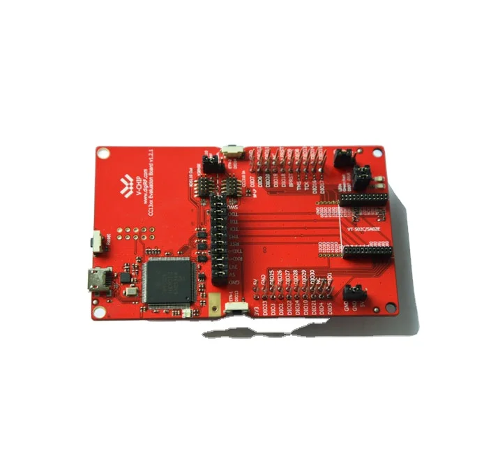
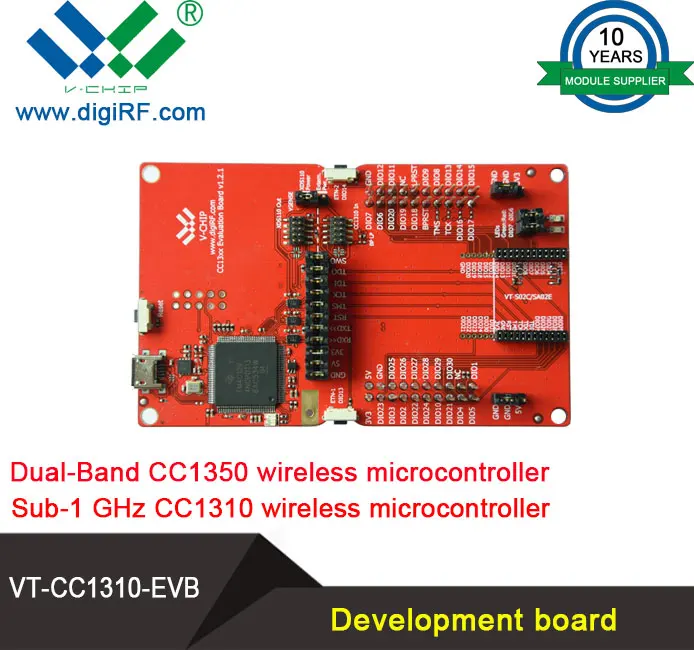
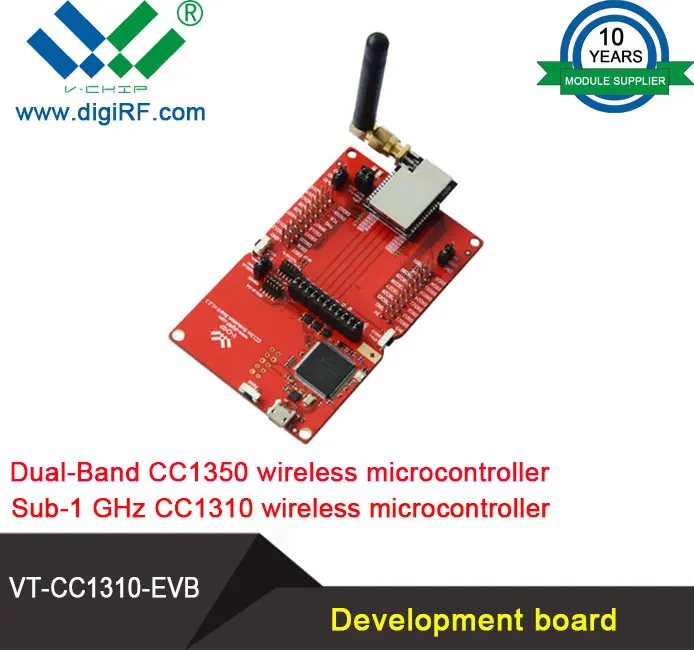
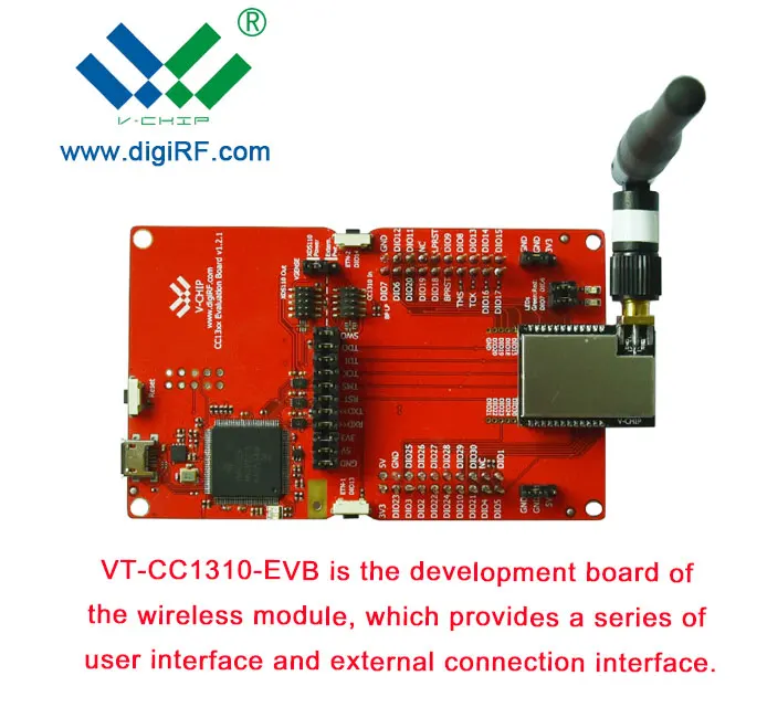
The VT-CC1310-EVB is the motherboard in the development kit for the Sub-1 GHz CC1310 wireless microcontroller, the Dual-Band (Sub-1 GHz and 2.4 GHz) CC1350 wireless microcontroller and the multistandard (ZigBee and 6LoWPAN, and ZigBee RF4CE) CC2650 wireless microcontroller. The board has a wide range of features, listed in Table 1 below.
Detail Parameters
Component
Description
XDS110
The XDS110 provides as debugger for SimpleLink MCUs, supports CCS and IAR. Play as programmer by using Flash Programmer 2.
Full-speed USB 2.0 interface
Easy plug and play access to full transceiver control using SmartRF Studio 7 PC software. Integrated serial port over USB enables communication between SimpleLink MCUs and PC.
Serial Flash
External flash for extra storage, over-the-air upgrades and more.
LEDs
Four general purpose LEDs for demo use or debugging.
Buttons
Three push-buttons for demo use and user interfacing.
Breakout pins
Easy access to GPIO pins for quick and easy debugging.
Table 1 -Available features on the VT-CC1310-EVB1 About this manual
Features
Related Product
Using the VT-CC1310-EVB
The VT-CC1310-EVB is a flexible test and development platform that works together with RF Modules base on SimpleLink wireless microcontroller from VCHIP.
An RF Module is a small module with wireless microcontroller, balun, matching filter, antenna, and I/O connectors. The module can be plugged into the VT-CC1310-EVB which lets the PC take direct control of the wireless microcontroller on the module over the USB interface.
Currently, VT-CC1310-EVB supports:
- VT-S02C Module
- VT-SA02C Module
- VT-SA02D Module
- VT-S03A Module
Some of the above modules come in variants combined with RF front-end. Such variants are called combo modules and are also supported by the VT-CC1310-EVB.
The PC software that controls the VT-CC1310-EVB + Module is SmartRF Studio 7. Studio can be used to perform several RF tests and measurements, e.g. to set up a Carrier Wave signal and send and receive packets.
The EVB + Module can be of great help during the whole development cycle for a new RF product.
- Easy and fast evaluated the RF Module performance.
- Verify your own software. Test the send function by transmitting packets from your software and receive with another board using SmartRF Studio 7. Then transmit using SmartRF Studio 7 and receive with your own software.
- Use the VT-CC1310-EVB as a debugger interface to the SimpleLink wireless microcontroller with CCS or IAR Embedded Workbench.
- Use the VT-CC1310-EVB as a programmer interface to the SimpleLink wireless microcontroller with Flash Programmer 2.
VT-CC1310-EVB Overview
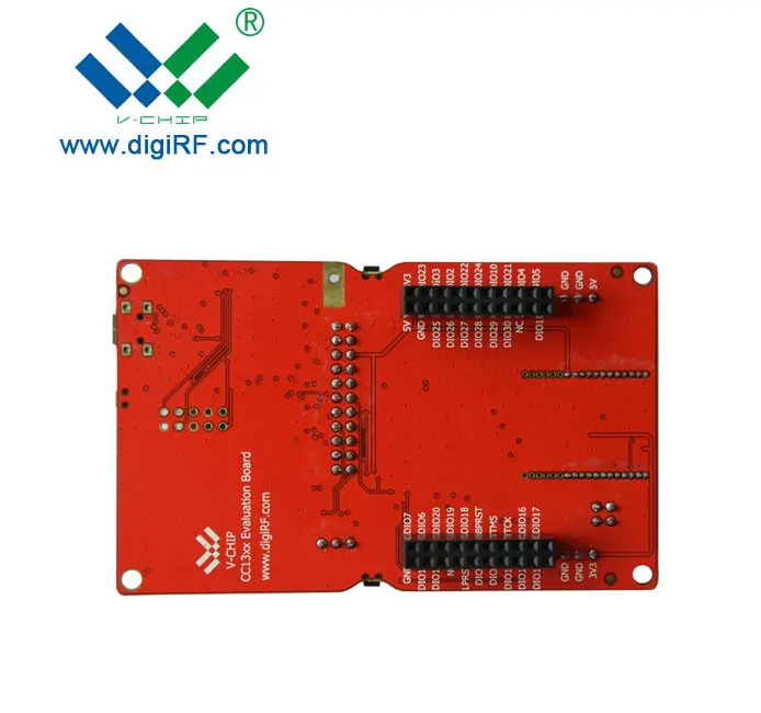
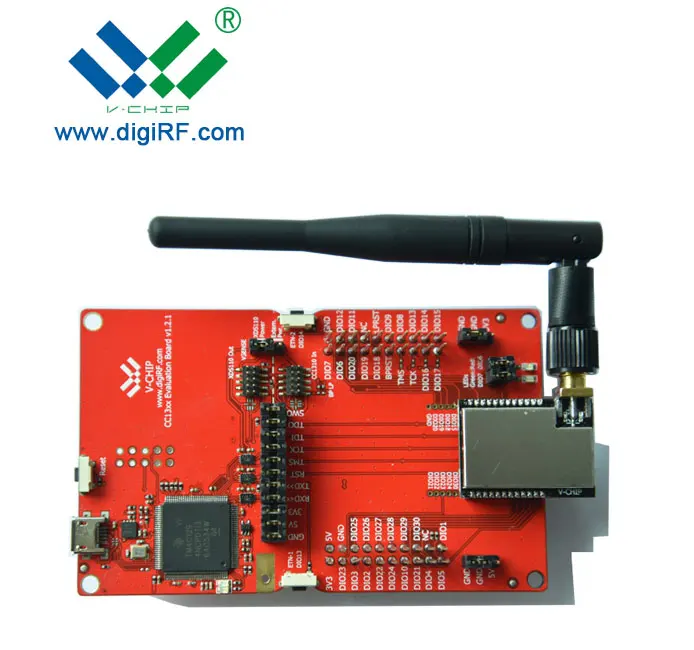
VT-CC1310-EVB acts as the motherboard for RF Modules from VCHIP. The board has several user interfaces and connections to external interfaces, allowing fast prototyping and testing of both software and hardware.
This chapter will give an overview of the general architecture of the board and describe the available I/O. The following sub-section will explain the I/O in more detail. Pin connections between the EVB I/O and RF Module can be found in section 5.5.
Applications
RF_1
RF_2
Signal Name
Description
Signal Name
Description
DIO2
GPIO / RXD
DIO29
GPIO
DIO3
GPIO / TXD
DIO28
GPIO
DIO4
GPIO
DIO27
GPIO
DIO5
GPIO
DIO26
GPIO
DIO6
GPIO / LED_RED
DIO25
GPIO
DIO7
GPIO / LED_GREEN
TDI
JTAG_TDI
DIO8
GPIO / FLASH_MISO
TDO
JTAG_TDO
DIO9
GPIO / FLASH_MOSI
TCK
JTAG_TCK
DIO10
GPIO / FLASH_SCLK
TMS
JTAG_TMS
DIO11
GPIO / FLASH_CS(2)
RST
GPIO / Button-3
DIO13
GPIO / Button-1
GND
Ground
DIO14
GPIO / Button-2
3V3
Power
DIO12(1)
GPIO
DIO1
GPIO(1)
DIO15
GPIO
DIO30
GPIO
DIO18
GPIO / SWO(3)
DIO24
GPIO
DIO19
GPIO
DIO23
GPIO
DIO20
GPIO / FLASH_CS(2)
DIO22
GPIO
GND
Ground
DIO21
GPIO
(1) In some case, VCHIP RF Module dose not pin-out all GPIOs, such as VT-S02C, VT-SA02C, VT-SA02D.
(2) Connected jumper between DIO11 and DIO20 to connect FLASH_CS to RF Module in case.
(3) SWO available in all pin-out RF modules.
Company Information
Packaging & Shipping
FAQ
Description
Reason and Solution
Can’t communication
1.The power supply connect not well, check the module VCC whether it is out of maximum rating.
2.The signal line connect not well, check the module SPI interface.
3.The settings of the transmitter module and receiver module are not the same. Check these modules’ register configuration.
4.Signal block. If the transmitter work with a high TX power, and the receiver was put at a short distance(<0.5m), maybe there is a signal block to make no communication.
Communication distance is too short
1.The application environment is too bad or the antenna is shield. Put the antenna to a better place outside or higher throw a coaxial line , replace it with a higher gain antenna.
2.The work space contains a same frequency interference source, or a strong magnetic field interference,power source disturbance. Try to change the carrier frequency or get far away from the source of the disturbance.
3.The power supply is not strong. Check the voltage and the current whether it is enough.
High data error
1.The power supply ripple is too big, Change the power supply.
2.Check the module register configuration, it is recommended to set as the CC1120-datasheet.
3.There is a carrier frequency interference, change the channel.
4.The antenna unmatched to the module RF interface, change another matched antenna.