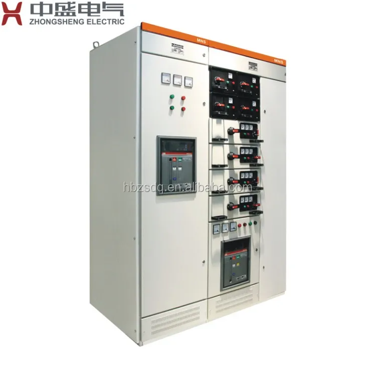
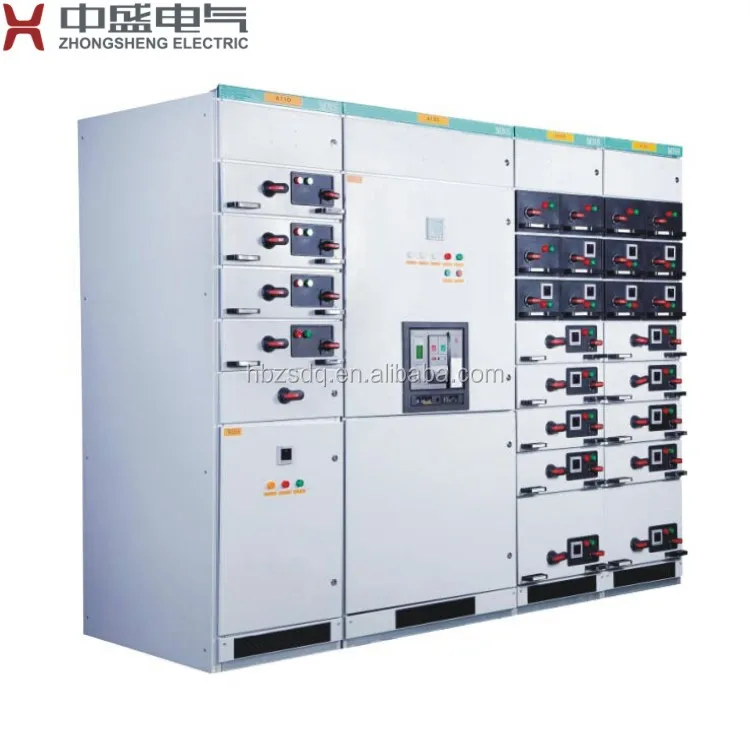
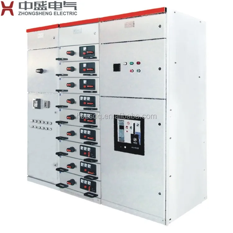
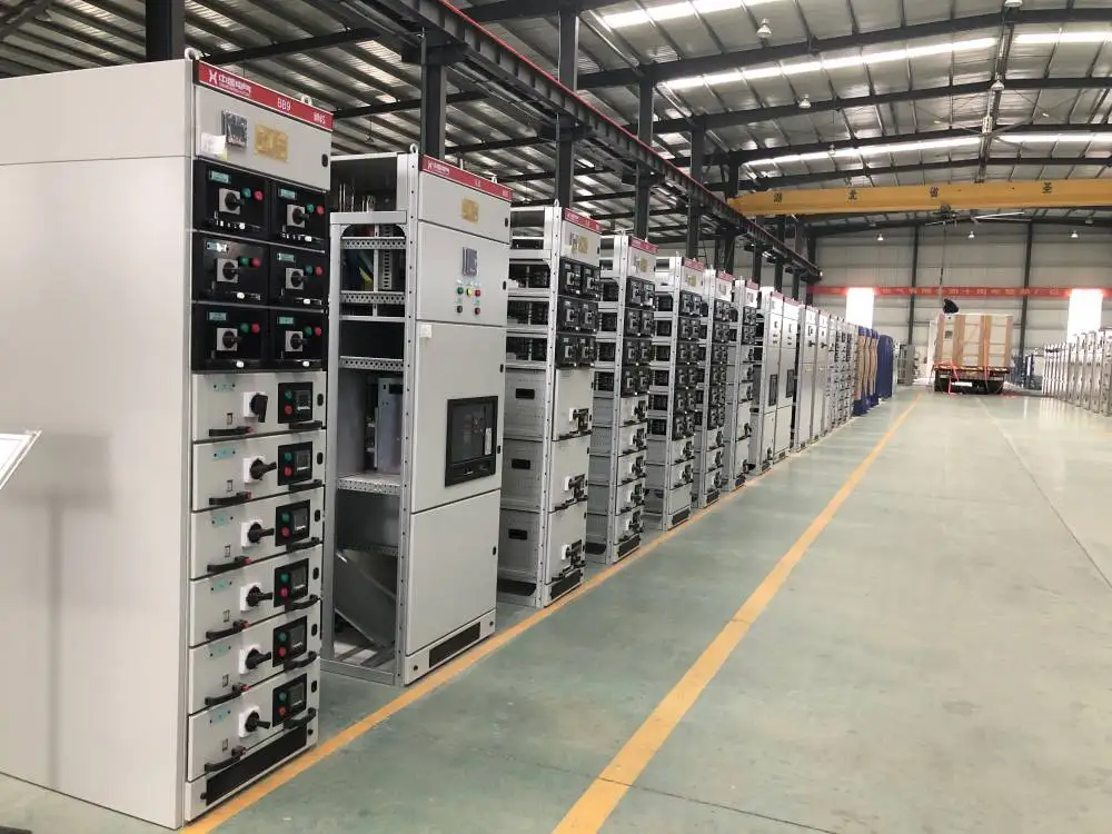
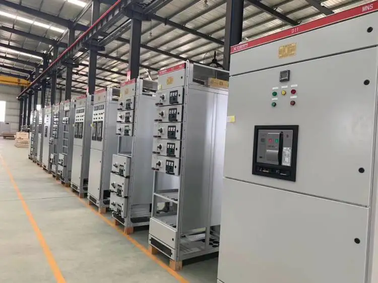
MNS mcc panel is a metal enclosed low voltage power circuit breaker switchgear offers excellent flexibility due to the modularity of both the electrical and mechanical design. The modularity enable customization of the structural design, interior arrangement and degree of protection. It's modular design is widely used for power distribution and motor control.
Technical parameter:
Rated insulation voltage
up to 1000V
Rated operating voltage
up to 690V
Rated frequency
50Hz, 60Hz
Main busbar
Rated current
up to 6300A
Rated peak withstand current
up to 250kA
Rated short-time withstand current
up to 100kA
Distribution busbar
Rated current
up to 2000A
Rated peak withstand current
up to 176kA
Rated short-time withstand current
up to 100kA
Size
Width
600mm, 800mm, 1000mm
Depth
800mm, 10000mm
Height
2200mm
Forms of separation
up to Form 4b
Degrees of protection
IP30
Mechanical design:
1. Frame construction: The basic elements of the MNS frame construction are "C" shaped steel profiles with a 25mm hole pitch. This 25mm equals the dimension of 1E used in MNS to define the area usage within the switchgear. Each cubicle is precision constructed by bolting horizontal and vertical profiles together, to form a rigid modular structure. The profiles are galvanic protected against corrosion.
2. Enclosure: MNS switchgear enclosure is made of sheet steel protected by galvanic coating and powder coating for maximum durability. The fixing of the enclosure with respect to doors, roof plates, rear and side walls is achieved with thread forming screws. Final construction varies depending upon the required degree of protection. In accordance with the general safety philosophy followed with MNS, each compartment and sub-compartment which requires access for commissioning, operation or maintenance, has its own door.
Functional compartments:
The switchgear is divided into compartments thus separating different functional areas: equipment compartment, busbar compartment, cable compartment.
Busbar system:
1. Main busbars: The MNS main busbar system is arranged in the rear of the switchgear. This assures a maximum distance between the busbars and the operator and maintenance staff. the main busbar system is fully separated from the equipment compartment as well as from the cable compartment. The busbar system and all associated parts are manufactured from copper.
2. Protective earth and neutral busbars: As a standard, protective earth and neutral busbars run horizontally with the front of the switchgear just above the base. The PE busbar is fastened to the frame to assure electrical continuity. Inside the cable compartment the run vertically, located on the front right hand side of the compartment.
3. Distribution busbars: A fully phase segregated and encapsulated 3 or 4 pole distribution busbar system runs the full height of the cubicle.
Withdrawable modules:
1. Modules can be easily exchanged under operational conditions thus assuring maximum flexibility.
2. Module operation: MNS modules are operated with the multifunction operating handle. This handle also activates the electrical and mechnical interlocking of the module and the module door. No further tools or unlocking devices are necessary to withdraw a module, thus replacing a module takes less than a minute. Replacement as well as retrofitting of modules can be performed under live condition, should plant operating procedures allow.
8E/4 and 8E/2 withdrawable module positions:
ON: Module is inserted, main switch closed, main and control circuit connected.
OFF: Module is inserted, main switch open, main and control circuit disconnected, padlocking possible.
TEST: Module is inserted, main switch open, main circuit disconnected, control circuit connected, padlocking possible.
MOVE: Module may be completely withdrawn from the switchgear.
ISOLATED: Module is withdrawn 30mm from the inserted position, main switch open, main and control circuit disconnected, padlocking possible.
8E, 16E and 24E main switch handle positions:
ON: Main switch closed.
OFF: Main switch open.
8E, 16E and 24E mechanism handle positions:
ON: Module is inserted, main switch closed, main and control circuit connected.
TEST: Module is inserted, main switch open, main circuit disconnected, control circuit connected, padlocking possible.
MOVE: Module may be completely witchdrawn from the switchgear.
ISOLATED: Module is withdrawn 30mm from the inserted position, main switch open, main and control circuit disconnected, padlocking possible.
Service condition:
1. Altitude: up to 2000m.
2. Ambient temperature: -15℃ to 40℃.
3. Relative humidity:
Daily average relative humidity: ≤ 95%.
Monthly average relative humidity: ≤ 90%.
4. Special service conditions: on request.
Installation foundation diagram:
Standards applied:
1. GB7251.1-2005: Low-voltage switchgear and controlgear assemblies Part 1: Type-tested and partially type-tested assemblies
2. IEC 60439-1:1999: Low-voltage switchgear and controlgear assemblies Part 1: Type-tested and partially type-tested assemblies
3. JB/T 9661-1999: Low voltage withdrawable switchgear assemblies