
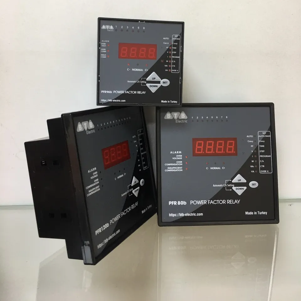
Power Factor Controller 6 Steps 96X96 Made In Turkey
EUR 60.00-62.00

Share on (60581564524):
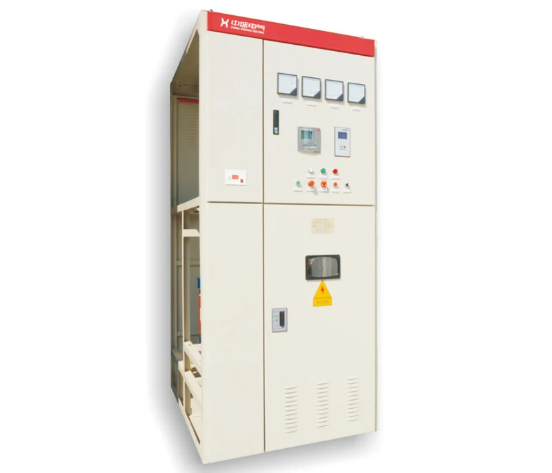
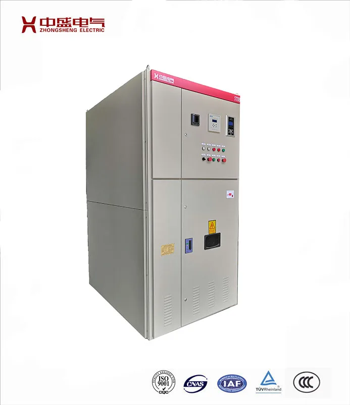
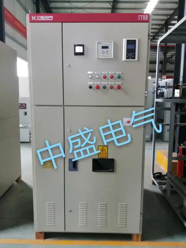
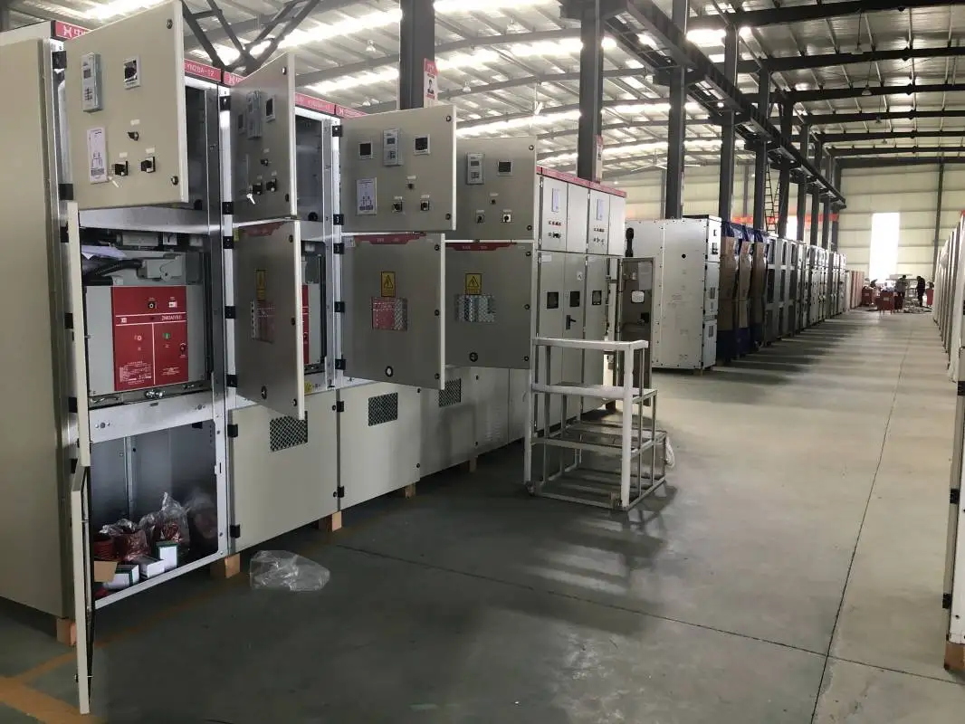
Product name: Automatic power factor correction unit

Description:
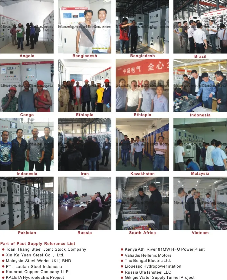
Automatic power factor correction unit is designed for industrial, commercial, and utility power systems involving motors, feeder circuits, and transmission and distribution lines where power factor improvement is required. Single stage and multi-stage, tuned or detuned filter banks can be supplied.
Standard ratings:
1. Rated voltage: up to 35kV, 3 phase
2. Rated frequency: 50Hz / 60Hz
Service condition:
1. Altitude: up to 1000m.
2. Ambient temperature: -10℃ ~ +40℃.
3. Relative humidity:
Daily average relative humidity: ≤ 95%.
Monthly average relative humidity: ≤ 90%.
4. Special service conditions: on request.
Enclosure size table:

Enclosure:
1. Protects the automatic power factor correction unit components against the external solid or liquid particles and also provide protection for human beings.
2. With hinged door and lockable door handle.
Automatic power factor controller:
1. Automatic power factor controller is the brain of automatic power factor correction unit, which switches ON / OFF the steps depending on the kvar required in order to maintain the power factor close to unity.
2. Digital display indicating all relevant parameters, such as power factor, current, voltage, frequency, active power, reactive power, capacitor step status, and etc.
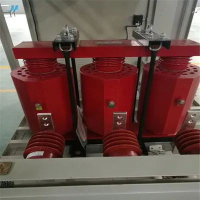
Capacitors:
1. Capacitors forms the core components in automatic power factor correction unit and plays a vital role in power factor correction. Proper selection of capacitors is very much necessary to comply with the applications.
2. Enclosed capacitor banks are for indoor, open rack capacitor banks are for outdoor.
Discharge resistors:
Reduce residual voltage to less than 50V within five minutes.
Detuned reactors:
1. Detuned reactors are designed to protection the capacitors by limiting inrush current and preventing amplification of the harmonics present on the network.
2. Connected in series with capacitors, detuned reactors are designed to withstand fundamental and harmonic currents.
Contactors:
1. Capacitor rated contactors with precharge coil, allows for immediate response to rapidly changing reactive loads, with no harm to the capacitors.
2. Contactors are used to switch capacitors in or out of service of each individual step. Prevent inrush current to a safe level when the capacitor steps are switched on.
3. The use of contactors may compromise the safety of persons and installations.
Current transformers:
Current transformer is used in automatic power factor correction unit for measurement purposes. It steps down load current to a low value output.
Protection devices:
Includes fuses, lightning arrestors, protection relays, and other protection devices to provide over voltage, under voltage, over current and other necessary protection.
Standard applied:
1. IEC 62271-1:2007 High-voltage switchgear and controlgear - Part 1: Common specifications
2. GB/T 11022-2011 Common specifications for high-voltage switchgear and controlgear standards
3. GB 50227-2008 Code for design of installation of shunt capacitors
4. DL/T 672-1999 Ordering specification for controlling device of adjusting voltage and reactive power in substation
5. GB/T 12325-2008 Power quality - Deviation of supply voltage
6. GB/T 12326-2008 Power quality - Voltage fluctuation and flicker
7. DL/T 653-2009 Specification of discharge coils for high voltage shunt capacitor for order
Installation foundation diagram of cabinet type:

Installation foundation diagram of open rack type:

Typical primary scheme:


New products from manufacturers at wholesale prices


