
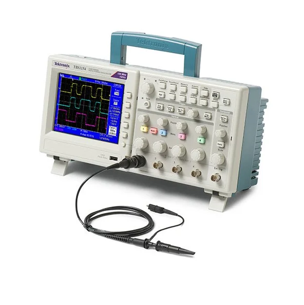
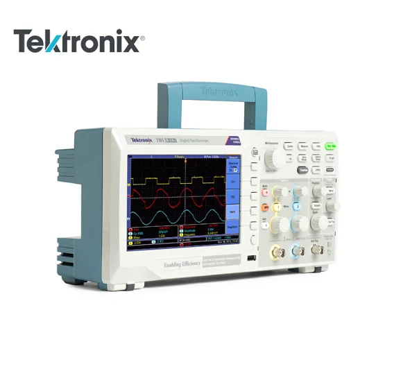
Original TBS1000B EDU Series Tektronix Digital Storage Oscilloscope TBS1152B EDU
- Category: >>>
- Supplier: Shenzhen Sweet Ocean Technology Limited
Share on (60727010247):
Product Overview
Description
TBS1000B Series Tektronix T Digital Storage Oscilloscopes TBS1152B-EDU


Horizontal system — Analog channels
- Time base range
- 30 MHz model 1
- 10 ns to 50 s/div
- 50 MHz and 70 MHz models
- 5 ns to 50 s/div
- 100MHz, 150MHz and 200MHz models
- 2.5 ns to 50 s/div
- Time base accuracy
- 50 ppm
- Horizontal zoom
- Horizontally expand or compress a live or stopped waveform
Input/Output ports
- USB interface
- USB host port on front panel supports USB flash drives
- USB device port on back of instrument supports connection to PC and all PictBridge®-compatible printers
- GPIB interface
- Optional
Data storage
- Nonvolatile storage
- Reference waveform display
- 2.5K point reference waveforms
- Waveform storage without USB flash drive
- 2.5K point
- Maximum USB flash drive size
- 64 GB
- Waveform storage with USB flash drive
- 96 or more reference waveforms per 8 MB
- Setups without USB flash drive
- 10 front-panel setups
- Setups with USB flash drive
- 4000 or more front-panel setups per 8 MB
- Screen images with USB flash drive
- 128 or more screen images per 8 MB (the number of images depends on file format selected)
- Save All with USB flash drive
- 12 or more Save All operations per 8 MB
A single Save All operation creates 3 to 9 files (setup, image, plus one file for each displayed waveform)
Acquisition system
- Acquisition modes
- Peak Detect
- High-frequency and random glitch capture. Captures glitches as narrow as 12 ns (typical) at all time base settings from 5 μs/div to 50 s/div
- Sample
- Sample data only
- Average
- Waveform averaged, selectable: 4, 16, 64, 128
- Single Sequence
- Use the Single Sequence button to capture a single triggered acquisition sequence
- Roll
- At acquisition time base settings of >100 ms/div
Trigger system
- External trigger input
- Included on all models
- Trigger modes
- Auto, Normal, Single Sequence
- Trigger types
- Edge (Rising/Falling)
- Conventional level-driven trigger. Positive or negative slope on any channel. Coupling selections: AC, DC, Noise Reject, HF Reject, LF Reject
- Video
- Trigger on all lines or individual lines, odd/even or all fields from composite video, or broadcast standards (NTSC, PAL, SECAM)
- Pulse Width (or Glitch)
- Trigger on a pulse width less than, greater than, equal to, or not equal to, a selectable time limit ranging from 33 ns to 10 s
- Trigger source
- Two channel models: CH1, CH2, Ext, Ext/5, AC Line
- Trigger view
- Displays trigger signal while Trigger View button is depressed.
- Trigger signal frequency readout
- Provides a frequency readout of the trigger source.
Waveform measurements
- Cursors
- Types
- Amplitude, Time
- Measurements
- ΔT, 1/ΔT, ΔV
- Automatic measurements
Period, Frequency, Pos Width, Neg Width, Rise Time, Fall Time, Maximum , Minimum , Peak-Peak, Mean, RMS, Cycle RMS, Cursor RMS, Phase, Pos Pulse Cnt, Neg Pulse Cnt, Rise Edge Cn, Fall Edge Cn, Pos Duty, Neg Duty, Amplitude, Cycle Mean, Cursor Mean, Burst Width, Pos Overshoot, Neg Overshoot, Area, Cycle Area, High, Low, Delay RR, Delay RF, Delay FR, Delay FF
Waveform math
- Arithmetic
- Add, Subtract, Multiply
- Math functions
- FFT
- FFT
- Windows: Hanning, Flat Top, Rectangular
- 2048 sample points
- Sources
- Two channel models: CH1 - CH2, CH2 - CH1, CH1 + CH2, CH1 × CH2
Autoset
- Autoset menu
- Single-button, automatic setup of all channels for vertical, horizontal, and trigger systems, with undo Autoset
- Square wave
- Single Cycle, Multicycle, Rising or Falling Edge
- Sine wave
- Single Cycle, Multicycle, FFT Spectrum
- Video (NTSC, PAL, SECAM)
- Field: All, Odd, or Even
- Line: All or Selectable Line Number
Autorange
- Automatically adjust vertical and/or horizontal oscilloscope settings when probe is moved from point to point, or when the signal exhibits large changes.
Frequency counter
- Resolution
- 6 digits
- Accuracy (typical)
- + 51 parts per million including all frequency reference errors and +1 count errors
- Frequency range
- AC coupled, 10 Hz minimum to rated bandwidth
- Frequency counter signal source
Pulse width or edge selected trigger source
Frequency counter measures selected trigger source at all times in pulse width and edge mode, including when the oscilloscope acquisition is halted due to changes in run status, or acquisition of a single shot event has completed.
The frequency counter does not measure pulses that do not qualify as legitimate trigger events.
Pulse Width mode: Counts pulses of enough magnitude inside the 250 ms measurement window that qualify as triggerable events (e.g. all narrow pulses in a PWM pulse train if set to "
Edge Trigger mode: Counts all pulses of enough magnitude.
- Channels
- 2 channel
Display system
- Interpolation
- Sin (x)/x
- Waveform styles
- Dots, vectors
- Persistence
- Off, 1 s, 2 s, 5 s, infinite
- Format
- YT and XY
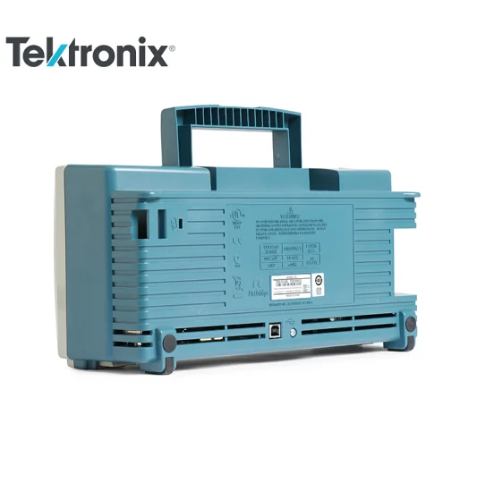
Power source
- Power source voltage
- 100 to 240 V ±10%
- Power source frequency
- 100 V to 240 V
- 50 Hz to 60 Hz
- 115 V
- 400 Hz ±10%
- Power consumption
- 30 W maximum
Physical characteristics
- Dimensions
mm in. Height 158.0 6.22 Width 326.3 12.85 Depth 124.2 4.89
- Shipping dimensions
mm in. Height 266.7 10.5 Width 476.2 18.75 Depth 228.6 9.0
- Weight
kg lb. Instrument only 2.0 4.3 ...with accessories 2.2 4.9
- RM2000B rackmount
mm in Width 482.6 19.0 Height 177.8 7.0 Depth 108.0 4.25
Environmental
- Temperature
- Operating
- 0 to +50 ºC
- Nonoperating
- –40 to +71 ºC
- Humidity
- Operating and nonoperating
Up to 85% RH at or below +40 ºC
Up to 45% RH up to +50 ºC
- Altitude
- Operating and nonoperating
- Up to 3,000 m (9,843 ft.)
- Regulatory
- Electromagnetic compatibility
- Meets Directive 2004/108/EC, EN 61326-2-1 Class A; Australian EMC Framework
- Safety
- UL61010-1:2004, CSA22.2 No. 61010-1:2004, EN61010-1:2001, IEC61010-1:2001
We Recommend


New Arrivals
New products from manufacturers at wholesale prices


