Rotary Kiln for Magnetization Calcining of Hematite, siderite and Limonite into Megnetite
- Category: >>>
- Supplier: Zhengzhou DynNor Industrial Machinery Co. Ltd.
Share on (60743216607):
Product Overview
Description
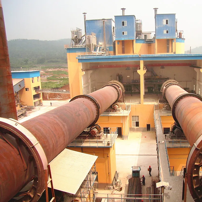
Rotary Kiln
Rotary kiln is a device used to raise materials to a high temperature for roasting or calcination in a continuous manner. Typical applying areas as follows:
· Cement
· Lime
· Refractory raw materials (bauxite, magnesite, etc..)
· kaolin
· Titanium dioxide
· Alumina
· Vermiculite
· Iron ore pellets, megnetization of iron ores
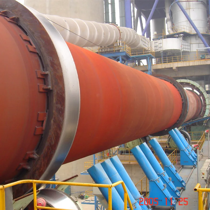
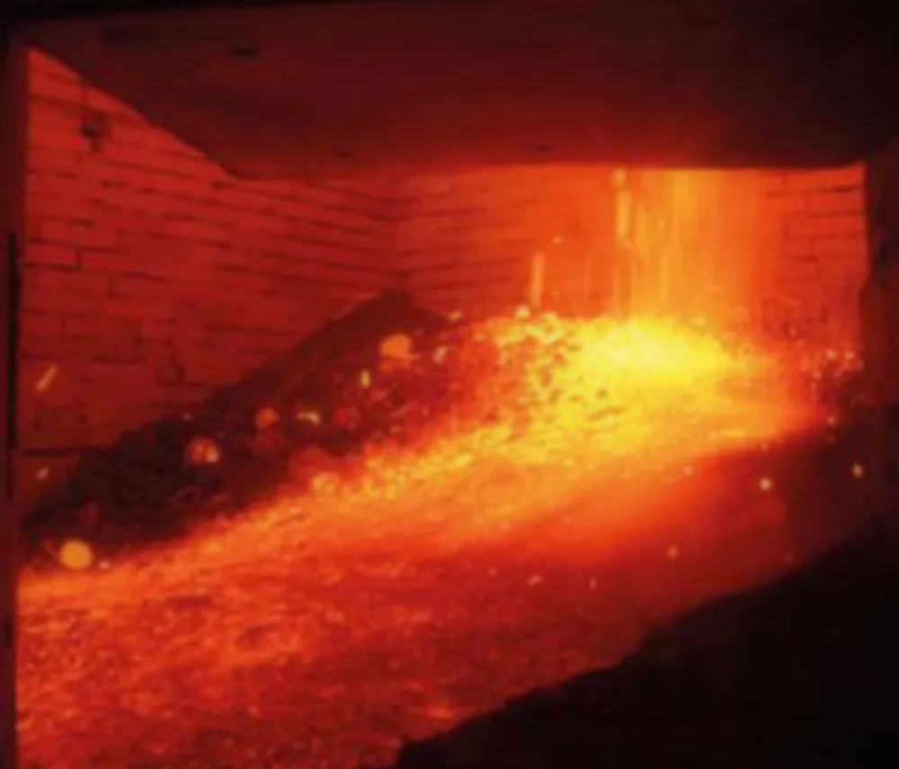
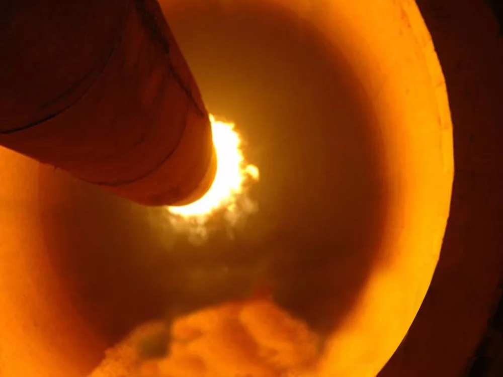
Principle of operation
The kiln is a slightly-inclined rotary cylinder, rotating slowly around its axis. Raw material is fed into the upper end of the cylinder. As the kiln rotates, material gradually moves down towards the lower end. Hot gas/flame pass along the kiln usually in the opposite direction against raw material. The hot gas may be generated in an external hot air stove, the flame is projected from a burner lance installed at the outlet end. The fuel for this may be gas, oil, pulverized coal or petrol coke.

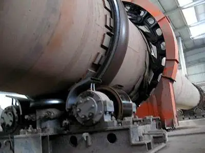
Structure of Rotary Kiln
The basic components of a rotary kiln are the shell, the refractory lining, support tyres (riding rings) and rollers, drive gear.

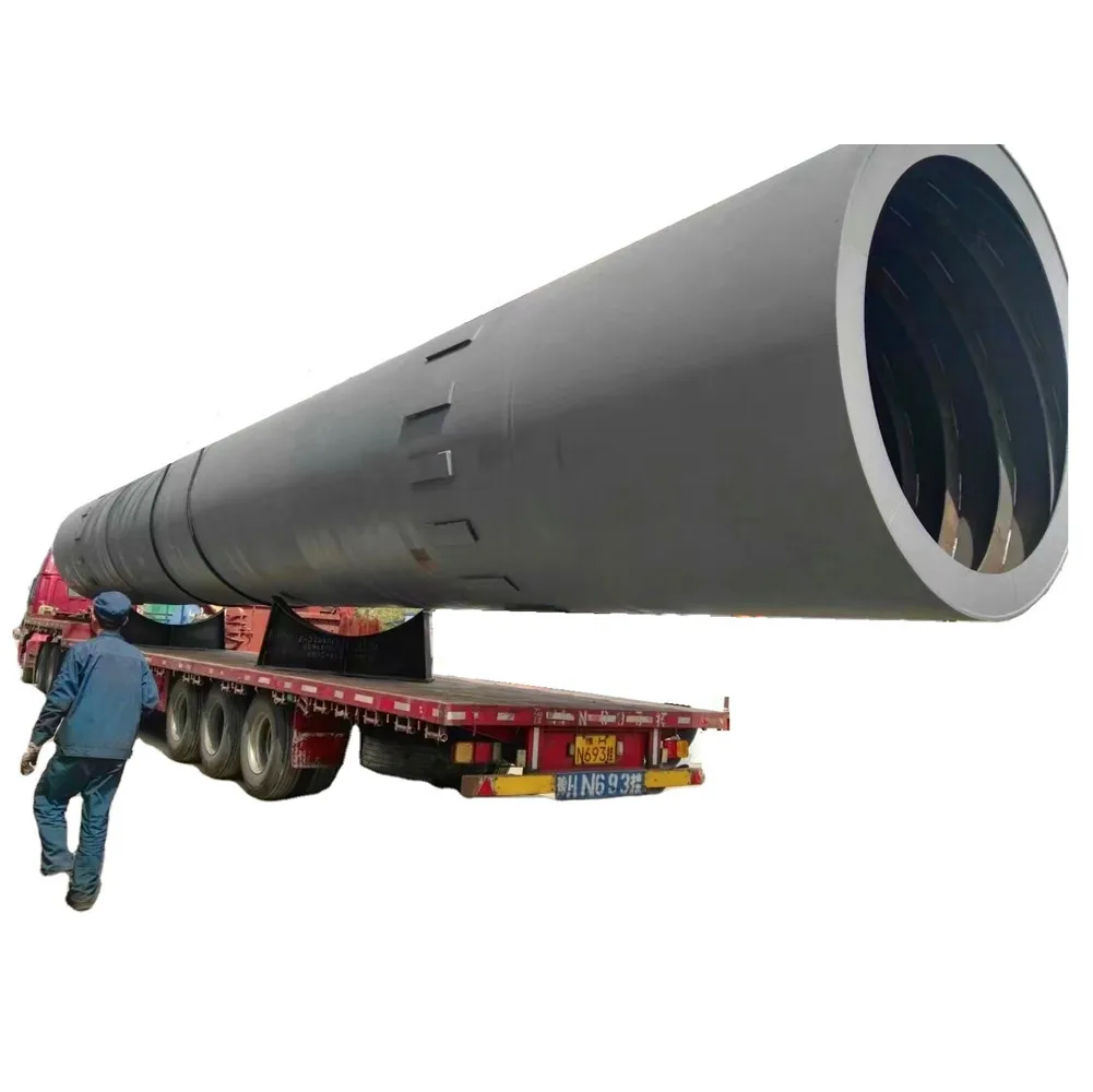
Kiln Shell
Kiln shell is made from carbon steel plate, usually from15 to 30 mm thick, welded together as a cylinder with length up to 150m and diameter up to 6 m or more. The kiln is usually installed on an east–west axis.
Upper limits on diameter are set by the tendency of the shell to deform under its own weight to an oval cross section, with consequent flexure during rotation. Length is not necessarily limited, but it becomes difficult to cope with changes in length on heating and cooling (typically around 0.1 to 0.5% of the length) if the kiln is very long.
Refractory Lining
The purpose of the refractory lining is mainly to protect the steel shell from the high firing temperature and corrosive material inside the kiln. The lining may be in refractory bricks or castables. The type of refractory depends upon the temperature inside the kiln and the chemical nature of the material under temperature. In cement kiln, the refractory life can be extended usually by maintaining a constant coating layer of the semi-molten material on the refractory surface. The thickness of the refractory lining is generally in the range 80 to 300 mm. A typical refractory lining will be capable of maintaining a temperature drop of 1000 °C or more between its hot and cold faces. The shell temperature needs to be maintained below around 350 °C in order to protect the steel from damage, and continuous infrared scanners are used to give early warning of "hot-spots" indicative of refractory failure.

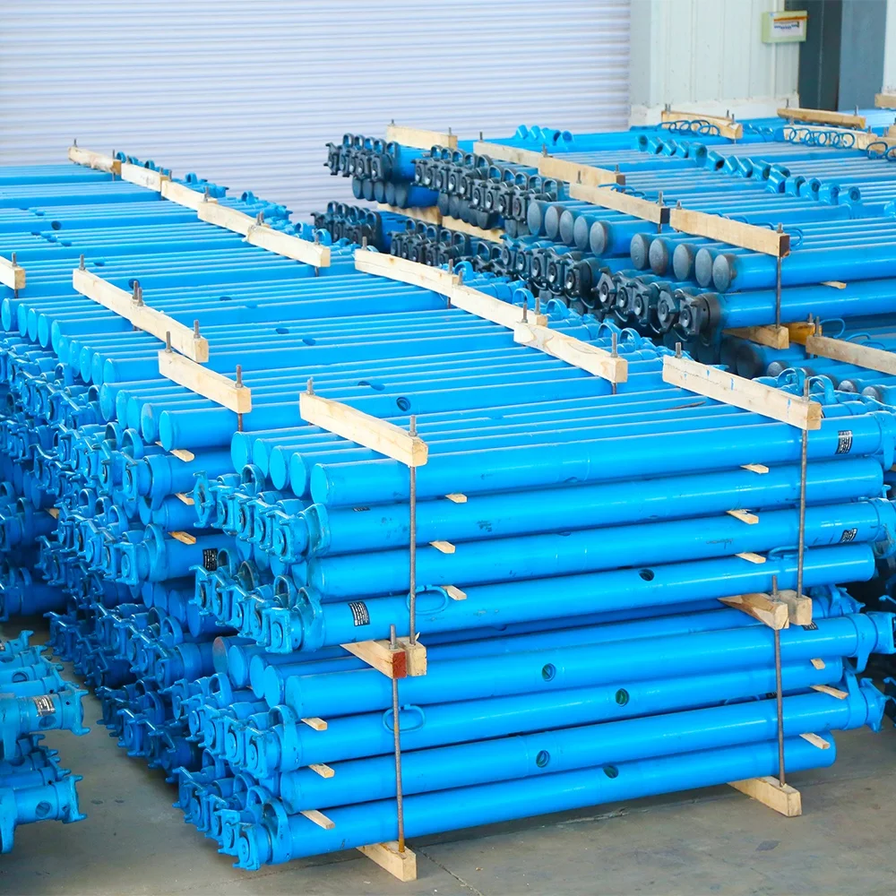
Tryes &Rollers
Tyres, also called riding rings, usually consist of a single annular steel casting, machined to a smooth cylindrical surface, which attach loosely to the kiln shell through a variety of "chair" arrangements. These require some ingenuity of design, since the tyre must fit the shell snugly, but also allow thermal movement. The tyre rides on pairs of steel rollers, also machined to a smooth cylindrical surface, and set about half a kiln-diameter apart. The rollers must support the kiln, and allow rotation that is as nearly frictionless as possible. A well-engineered kiln, when the power is cut off, will swing pendulum-like many times before coming to rest. The mass of a typical 6 x 60 m kiln, including refractories and feed, is around 1100 tonnes, and would be carried on three tyres and sets of rollers, spaced along the length of the kiln. The longest kilns may have 8 sets of rollers, while very short kilns may have only two. Kilns usually rotate at 0.5 to 2 rpm, but sometimes as fast as 5 rpm. The Kilns of most modern cement plants are running at 4 to 5 rpm. The bearings of the rollers must be capable of withstanding the large static and live loads involved, and must be carefully protected from the heat of the kiln and the ingress of dust. In addition to support rollers, there are usually upper and lower "retaining (or thrust) rollers" bearing against the side of tyres, that prevent the kiln from slipping off the support rollers.
Drive Gear
The kiln is usually turned by means of a single Girth Gear surrounding a cooler part of the kiln tube, but sometimes it is turned by driven rollers. The gear is connected through a gear train to a variable-speed electric motor. This must have high starting torque in order to start the kiln with a large eccentric load. A 6 x 60 m kiln requires around 800 kW to turn at 3 rpm. The speed of material flow through the kiln is proportional to rotation speed, and so a variable speed drive is needed in order to control this. When driving through rollers, hydraulic drives may be used. These have the advantage of developing extremely high torque. In many processes, it is dangerous to allow a hot kiln to stand still if the drive power fails. Temperature differences between the top and bottom of the kiln may cause the kiln to warp, and refractory is damaged. It is therefore normal to provide an auxiliary drive for use during power cuts. This may be a small electric motor with an independent power supply, or a diesel engine. This turns the kiln very slowly, but enough to prevent damage.
Typical Technical Data
| Model | major technical data | main reducer | main motor | support rollers (sets) | weight (t) | |||||
speed (r/min) | angle (%) | output (t/h) | Model | Speed ratio | Model | power (kw) | speed (r/min) | |||
| Φ1.2×25 | 0.5-1.6 | 3 | 0.7-1.0 | PM650 | 40.17 | JZTY71-4 | 22 | 1200/120 | 3 | 34 |
| Φ1.4×33 | 0.39-3.96 | 3 | 0.9-1.3 | JZQ750-1 | 48.58 | JZT-72-4 | 15 | 1000/400 | 3 | 47 |
| Φ1.6×32 | 0.158-0.258 | 3 | 1.2-1.9 | PM750 | 48.57 | JZJY61-4 | 15 | 1200/120 | 3 | 46.82 |
| Φ1.9/1.6×36 | 0.53-1.59 | 4 | 2.5-3.0 | JZQ750-1 | 48.58 | JZT-72-4 | 30 | 1200/400 | 3 | 53 |
| Φ2.1/1.8×36 | 0.5-1.51 | 4 | 2.8-4.2 | UT2-110 | 163.36 | JZS-81 | 30/10 | 1410/470 | 3 | 75 |
| Φ1.8×45 | 0.66-1.98 | 4 | 3.0-3.6 | UT2-110 | 163.36 | JZS-81 | 30/10 | 1410/470 | 3 | 80 |
| Φ2.0×45 | 0.32-2.32 | 3.5 | 3.2-4.5 | ZS145-11 | 157 | YCT280-4A | 30 | 1320/132 | 3 | 100 |
| Φ2.2×50 | 0.125-1.25 | 3.5 | 3.5-4.8 | ZS145-11 | 157 | YCT280-4A | 30 | 1320/132 | 3 | 130.71 |
| Φ2.5×50 | 0.516-1.549 | 3.5 | 7.0-8.0 | ZS165-7 | 99.96 | YCT355-4A | 55 | 1320/440 | 3 | 167.5 |
| (9-11) | ||||||||||
| Φ3×48 | 0.3309-3.309 | 3.5 | 21-25 | ZL130-14 | 32.11 | ZSN4-250-21B | 90 | 1000/100 | 3 | 237 |
| (35-42) | ||||||||||
| Φ3.2×50 | 0.398-3.975 | 3.5 | 25-35 | ZL130-16 | 40.85 | ZSN4-280-11B | 190 | 1500/150 | 3 | 263 |
| (45-50) | ||||||||||
| Φ3.3×52 | 0.391-3.91 | 3.5 | 26-38 | ZSY500-28 | 27.707 | ZSN4-315-082 | 190 | 1000/100 | 3 | 280.8 |
| (48-55) | ||||||||||
| Φ4×60 | 0.396-3.96 | 3.5 | 104 | ZSY630-35.5 | 34.601 | ZSN4-355-092 | 315 | 1000/100 | 3 | 487.5 |
| Φ4.2×60 | 0.4165-4.165 | 3.5 | 116 | ZSY710-35.5 | 35.526 | ZSN4-355-12 | 420 | 1000/100 | 3 | 576.1 |
| Φ4.3×62 | 0.398-3.98 | 3.5 | 125 | ZSY710-35.5 | 35.714 | ZSN4-355-12 | 420 | 1000/100 | 3 | 598.5 |
| Φ4.8×74 | 0.35-4 | 4 | 208 | JH710C-SW305-40 | 42.226 | ZSN4-400-092 | 630 | 1500/130 | 3 | 841 |


We Recommend
Silica Sand Washing and Flotation Process for Pure SiO2
$30,500.00-35,000.00
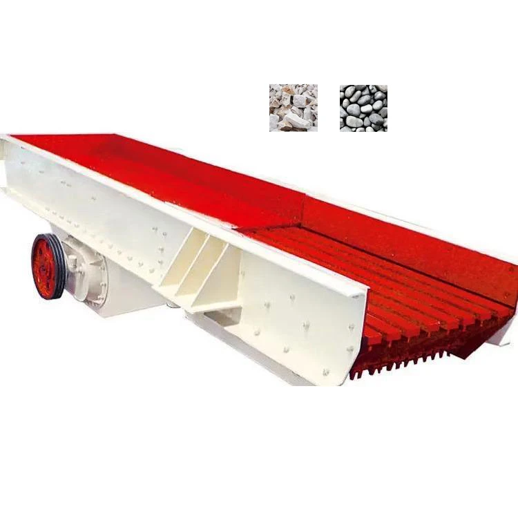
High Efficiency Mining Quarry Bulk Stone Rock Vibrating Feeder
$8,500.00-10,000.00
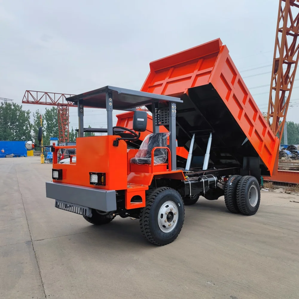
Factory Direct Sale 60 Ton Mining Dump Truck Heavy Mining Equipments Truck
$25,000.00-41,000.00
New Arrivals
New products from manufacturers at wholesale prices


