
GOWORLD square wave Pulse receiver CTS 8077PR Olympus flaw detection
- Category: >>>
- Supplier: Guangdong Shantou Goworld Electronic Co. Ltd.
Share on (62020644053):
Product Overview
Description
Product Description
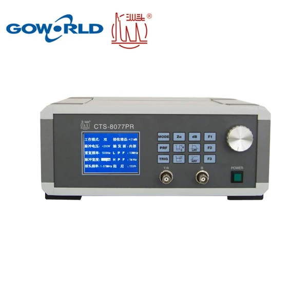
As a pulser-receiver Newly developed by Shantou Goworld Co.,Ltd.,CTS-8077PR lives up to the requirements of the transducer testing system by EN12668:2000 standard. It is featured by low-noise and broadband receiver-amplifier. Moreover, it is equiped with advanced transmission circuit constituted by high-performance square wave pulser and high-voltage circuit.
Coupled with digital oscilloscope,this device can serve the function of assessing the acoustic property of ultrasonic probe and that of working out the performance index. It can also be applied in such occasions as ultrasonic flaw detecting system, thickness gauging, material charateristics measuring, and so on.
Appearance of the device will make itself a new spot in the domestic ultrasonic market and assume the best substitute for foreign counterparts. Which endows it with high performance-to-price ratio.
Feature:
- Broadband square wave pulser.
- Pulse width ranging adjustably from 25ns to 6500ns, minimum step 5ns, corresponding to the probes as from 80kHz to 20MHz.
- Pulse Voltage varying adjustably from -25V to -400V, by the step of 25V.
- Optional pulse repetitive frequency, with the highest up to 5 kHz.
- Broadband (30MHZ) pulse receiver.
- 60dB RF Gains,1 dB step to adjust.
- 50dB RF Attenuations, 1dB step to adjust.
- 10MHz or 30MHz optional low-pass filter.
- 1kHz or 1MHz optional high-pass filter.
- USB interface, PC synchronized control and PC synchronized control software and user-developing package.
Specification:
Waveform comparison by Energizing TOFD probe:
| X077PR | CTS-8077PR | |
| 10MHZ Voltage: 200v Pluse: 50ns |  |  |
Center Frequency:8.28MHz Absolute bandwidth:7.5MHz | Center Frequency:7.5MHz Absolute bandwidth:8.6MHz | |
| 5MHZ Voltage: 100v Pluse: 100ns |  |  |
Scope:
Detection: thickness guage; velocity measurement; spectrum analysis; transducer properties testing; other materials and process monitoring; as EN-standard according probe-calibrating system.
Take the UT transducers (probes) for example:
To test the pulse width of the echo wave, center frequency, -6dB relative bandwidth, and relative pulse sensitivity of echo wave by the CTS-8077 pulser-receiver and "Goworld-ed" probe-testing software in concert.
Tip 1 for the organization:
1.CTS-8077PR linked up with PC via USB cable, and The T/R connector of 8077 with UT transucer by co-axial shielded probe cable, working mode: Mono.
2.The OSC connected with PC through cross network cable, and proof-reading of the data acquired by the PC from OSC.
3.The CH1 (channel 1)-probe connected with the cable.
Diagram 4 shows that the OSC probe acquires output signals from the transducer without passing through the PR, which requires no bandwith limit on the receiving circuit of the PR.

Testing Process
1.In reference to Diagram 4, put all the units in their place and make sure they run well.
2.Make sure there's waveform data to the PC from the OSC.
3.Set up the OSC, turn on "CH1" and "MATH", and set the "MATH" as "FFT algorithm", set the signal source as "CH1".
4.Set the working mode of CTS-8077 as "Mono", and set other paras according to the transducer. As we're now experimenting the 2.5P20 Series, the settings should be followed as:
Working Mode:Mono;Gain:0dB;Pulse Voltage:-200V;Triggering Source:Inner;
PRF:500Hz;LPF:30MHz;Pulse Width:200ns;HPF:1kHz;Damping:50Ω
Packaging & Shipping

Related products

Company Information

Back to home
We Recommend


New Arrivals
New products from manufacturers at wholesale prices


