

- Home
- Categories
- Long Lifetime DC Brushless Motor Driver 3000W
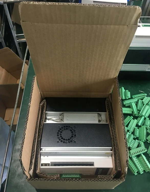
Long Lifetime DC Brushless Motor Driver 3000W
- Category: >>>
- Supplier: Shenzhen Dingtuoda Electromechanics Co. Ltd.
Share on (62033429178):
Product Overview
Description
Product Description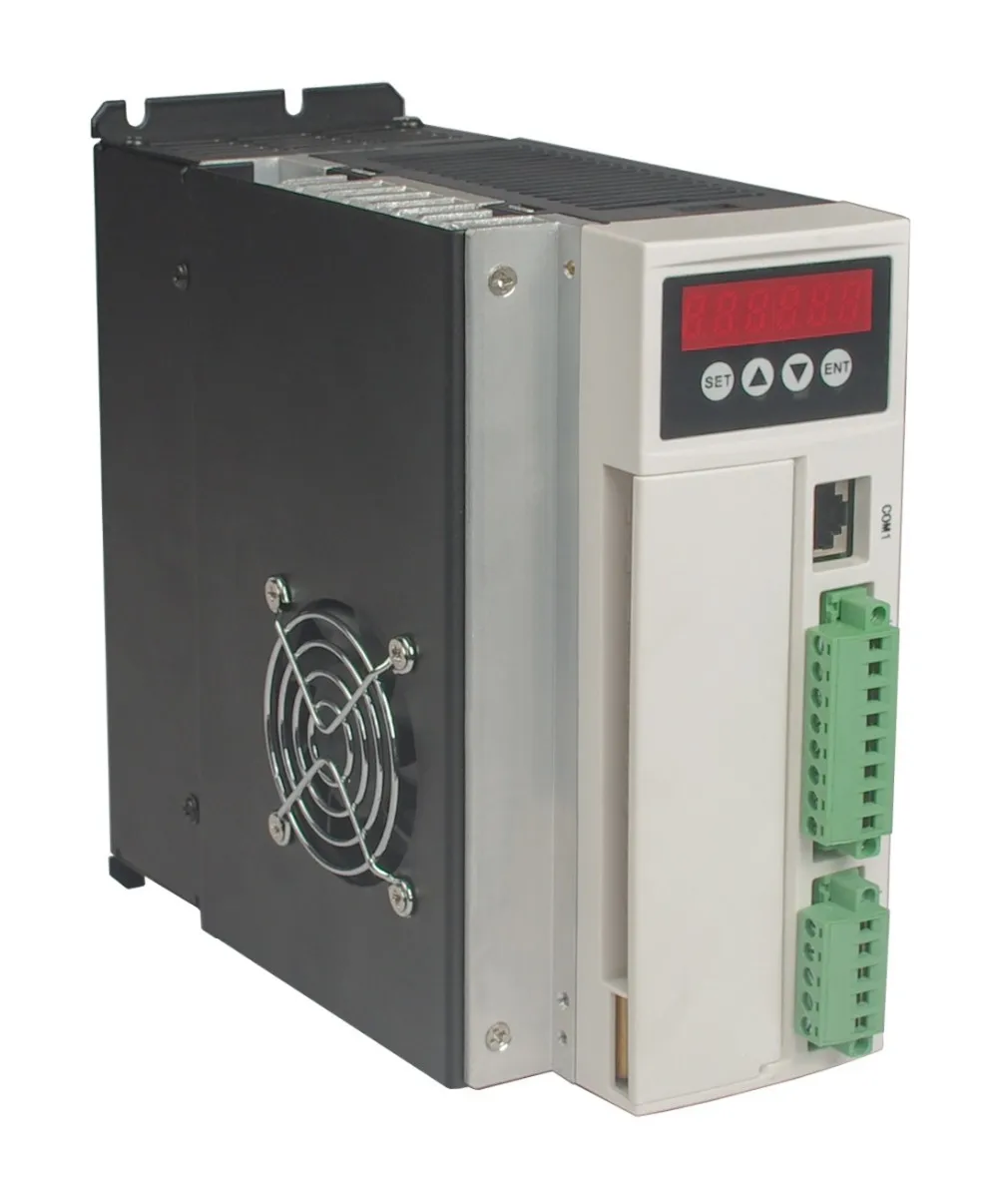


Summary
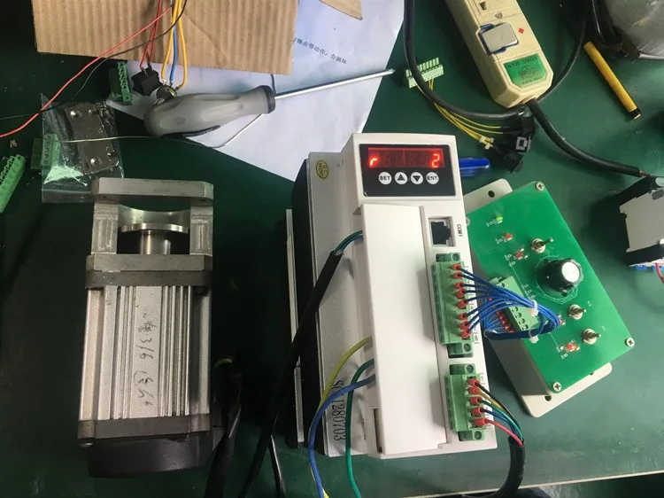
220VAC BL drives is a powerful driver designed by Dingtuo Technology independence which is assorted with the advanced motion control industrial. The drives adopt the latest DSP specialized for motor as the core technical matched with high speed digital logic chips and high quality power module. It gets the advantage on highly integration, small volume, well protection, high reliability etc. This drives can provide: panel speed adjust command, external simulative voltage, external potentiometer, pulse width speed adjust etc.
The main function of the drive is as follows:
●Choose a variety of speed adjustable, including input voltage setting, drive's internal speed setting,
communication interface setting etc.
●Complete isolation of electric supply, and Hall signal interface, guarantee of security.
●Digital display panel, abundant display content settings, abundant feature setting.
●The drive device of automatic protection, automatic control of current, with undervoltage and overvoltage, blocking and hall fault lamp protection function.
●The standard series can provide 2 times or even higher short-term overload current, different products with different supply.
Product features:
1. System Characteristic
Input Voltage: 110/220/380VAC, 50/60Hz
Continuous Output current: 12A
Max. Output current: 30A
Working temp.: 0~+45°C
Storage temp.: -20~+85°C
Working & storage humidity: <85% no frosting
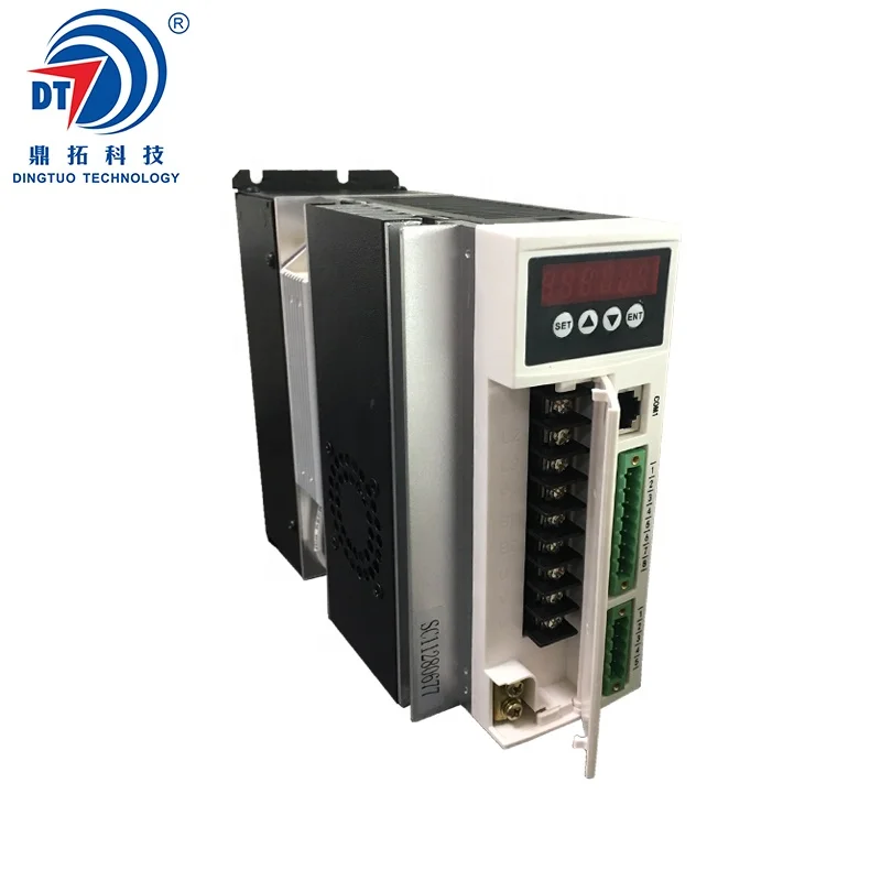
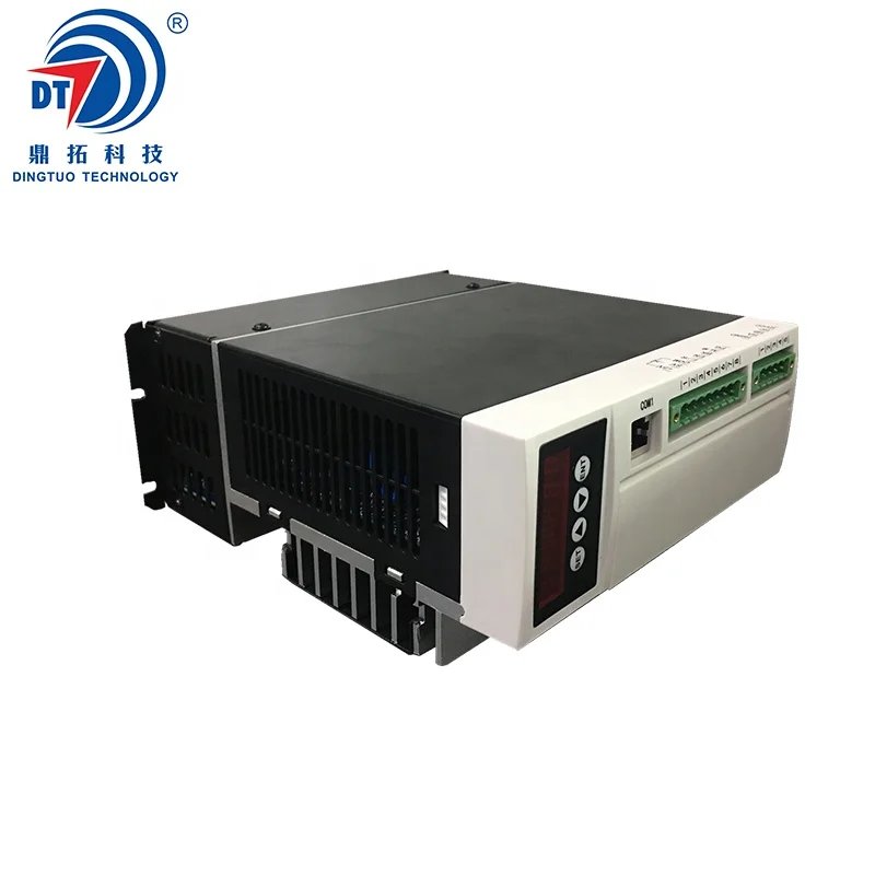
Structure: wall-mountable box type
Dimension:L180 x W85 x H190mm
2. Basic Characteristic
Cooling: Radiator
Control terminals: Isolation
Protection: Over load, over heat, over speed, over voltage, lost voltage will cause the power abnormity
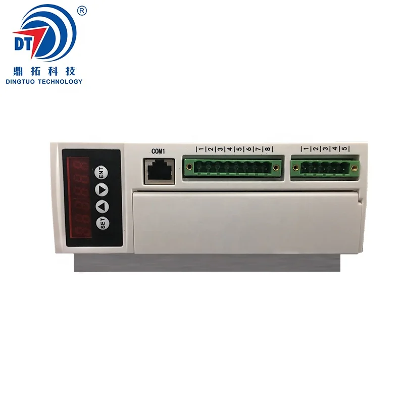
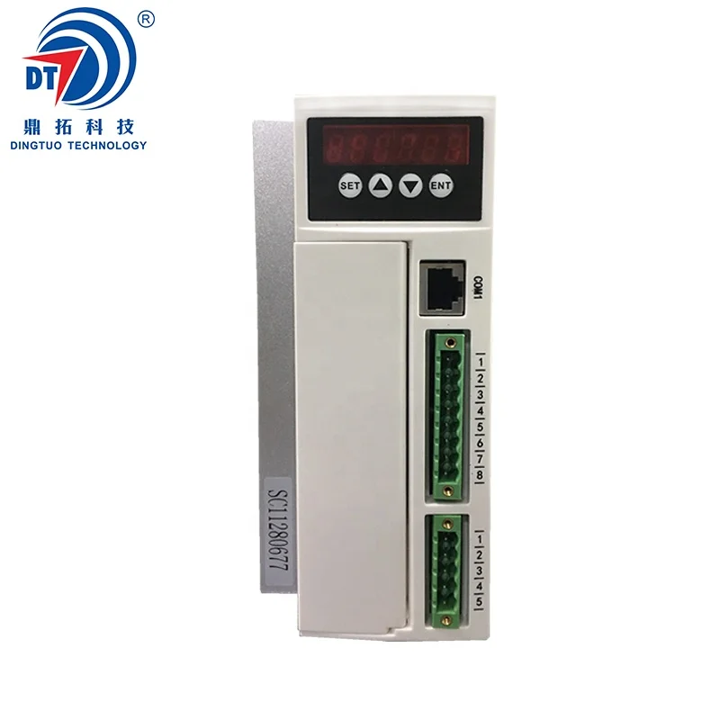
Panel: 6 digit LED display, 4 digit keypad operation
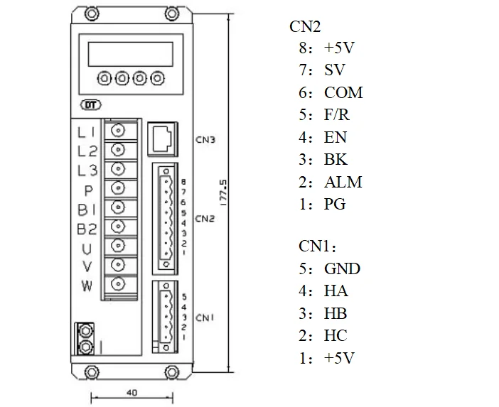
Terminal Function Specification
| No. | Terminal Name | Signal | Function |
| 1 | L1(L)(R) | Power input of main circuit | Main circuit power input terminal AC220V 50Hz, Connect L1 and L2 while using single phase voltage 220V |
| 2 | L2(N)(S) | ||
| 3 | L3(T) | ||
| 4 | P | High voltage DC bus line terminal | DC bus line terminal in driver, rated power 315V, Part of the products are built in brake resistance ,When using external brake resistance, connect it with P,B2. NOTE !!! Can not simultaneously access P and B1 |
| 5 | B1 | High voltage DC bus negative terminal | |
| 6 | B2 | External brake resistance | |
| 7 | U | Output | The motor output terminals must be connected with U,V,W one-to- one. Attention: do not reverse the motor by exchange 3 phase terminals, it is completely different with asynchronous motor |
| 8 | V | ||
| 9 | W | ||
| | PE | Protection | The release way is supplied for protection motor and drive when current leakage |

3) Parameters setup
3.1 Parameters P1
This series characteristics are used to set up some functions by clients self, they can be self-adjust according to clients' different demand. They are operation functions, have no relation with fundamental characteristics of driver.
Parameter P1
| Parameter Name | Parameter No. | Set numerical range | Factory default | Function specification |
| Display optional | P1.0 | 0~9 | 0 | 0: Display real speed 1: Display DC voltage of main circuit 2: Display external analog input 3: Display motor current 4: Display driver's real-time power 8: Duty ratio 9: Preserve |
| Internal running speed | P1.1 | 0~9999 | 2000 | When choose internal speed, the data will decide motor's speed(view P1.2) |
| Choose signal sourcing of speed | P1.2 | 0~2 | 1 | 0: Internal instruct speed (P1[0] is internal speed, when motor running, to up speed , to reduce speed) 1: Analog input, using CN2 signal of 7 pin SV signal as motor's speed. 2: Communication order control (Temporarily unavailable) |
| Direction setting | P1.3 | 0~1 | 0 | 0: CW 1: CCW |
| Choose signal sourcing of start-stop | P1.4 | 0~2 | 1 | 0: Button by hand control(ENT is start-stop, SET is reverse motor, +/- is for up and reduce speed) 1: External terminal control: using 4pin signal of CN2 to start and stop motor 2: Communication order control |
| Pole pairs of motor | P1.5 | 0~99 | 2 | If the setting is not right, it will lead to the display of the speed and the actual speed does not match attention: pole pairs=pole/2 |
| Driver location | P1.6 | 0~255 | 1 | The driver location when Using communication to control motor |
| Speed scale factor | P1.7 | 0~99999 | 1520 | KP. Scale factor using for PID speed control (KP) |
| Speed integrating factor | P1.8 | 0~99999 | 320 | Integrating factor using for PID speed control(KI) |
| Accelerated speed | P1.9 | 1~60000 | 6000 | The parameters is proportional to accelerated speed (unit: rps), 1000 means accelerate 1000 turn per min. the real accelerated speed is based on loading of motor |
| Decelerated speed | P1.10 | 1~60000 | 6000 | Unit conversion / minute (RPM), when the analog input to the maximum value of the corresponding motor speed |
| Analog input speed range | P1.11 | 0~99999 | 3000 | |
| Analog input dead band | P1.12 | 0~3300 | 100 | The function is used to set input voltage when motor speed is 0 (unit: mV) |
| Manual operation to adjust speed equivalent | P1.13 | 1~999 | 1 | Use bottom to change the speed equivalent under internal speed type ( speed changed per press) |
| Recover default parameters | P1.14 | 0~1 | 0 | Set up 1 then quit setting, connecting the power again, all parameters will recover to default value. |
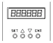
3.2 Control Panel Operation
Display instruction: total 6 digital tube shows "888888", the light most is the first and the lowest.

As picture on left, there are 4 keys on the panel,
"SET": press this key can enter or quite P1 setup menu
"▲"and "▼": "+"and "-",to choose the function and adjust the parameters.
"ENT": "confirmation" and "operation", when setting parameters, press this button to enter adjustment interface and jump. Under trial operation type, press ENT to start or stop motor.
Attention: The adjustment is forbidden if the adjusted value is larger than the maximum allowed, the bottom will be no response.
How to set parameters
Example:
Demand: set internal speed (P1.1) to 1000rpm/min
Operation step as below:
1.After connecting with power, display "H 0", the driver is standby, press "SET", will display"P0. 0", press "▲"until displayed "P0.6", press "ENT", display"00000", and the first of light most is flashing, press" ▲", change into "1", press "SET", display "P0. 6" . This step is to complete the P1 parameter set to unlock
2. Press "SET", display "P1 0", the driver is entering P1 setting state
3.Press "▲", until display "P1. 1"
4. Press "ENT", display "2000", and the first of light most is flashing
5. Press "ENT", until the flashing is moving to the fourth position
6. Press "▼", change into "1000"
7. Press "SET", display "P1. 1", the parameters had been set up and save automatic
8. Press "SET" again, back to standby state, display "H 0". Now, the new parameters adjustment had finished and take effect
Attention: 1. after adjustment, the driver need to connect with power again, then the new parameters will take effect
2. The parameters with "★" in the list can not been adjust when motor working
3. The adjustment is forbidden if the adjusted value is larger than the maximum allowed, the bottom be will no response
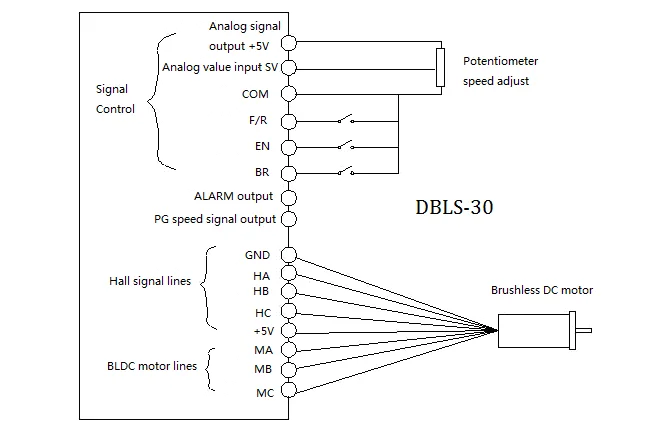
Wiring Diagram

Functions
Speed adjustment method
This driver provide below two adjust methods for the user to choose:
Analog voltage adjustment speed: the terminals of external potentiometer connect to the +5v terminal in signal control and COM, connect the regulator terminal to SV, not only make it possible to adjust speed by external potentiometer (10K~100K), but also can achieve speed adjust through other control unit (Such as PLC, Microcontroller, etc) input analog voltage to SV. The acceptance of SV is DC 0V~+5V, and the corresponding motor rotate speed is 0 to rated speed.
You also can use external digital signal to adjust speed: apply PWM with 5V amplitude and 1KHz~2KHz Frequency between SV and GND to adjust the speed. The motor rotate speed will adjust by the duty radio liner adjustment.
Panel control mode: This mode can be completely independent of the external control signal to start the motor, it is very useful for equipment debugging and maintenance when need to start the motor, or check the motor and drive system is not normal, and so on,
Set the target speed of the motor running by setting the system parameter P1.1. After setting the speed, press the "ENT" button, the motor will start and accelerate to the set speed. In the operation process of the motor, it can be manual speed, long press panel "▲" and "▼" button to adjust the speed value.
Motor operate/stop control (EN)
You can control the brushless motor to run or stop by controlling the terminal "EN" and "COM" connecting. The motor will run when we connect the terminal "EN" to "COM"; when shut down, the motor will stop naturally.
Motor rotation direction control ( F/R )
You can control the motor rotation direction by controlling the terminal "F/R" and "COM" connecting. When connect terminal "F/R" to terminal "COM", the motor will run at CCW (view from motor output side), and when shut down, the motor will run at another direction. When CW/CCW is switched on in the running state, the motor will automatically stop and then start running in the opposite direction. (Different models with different rotation direction, user needs to confirm the steering.)
Emergency Stop (EMG)
Through the control of the terminal COM and the terminal EMG to control the motor stop or running.The motor is running when the terminal EMG and terminal COM shut off, stop when connected, and display "br" on the panel.
Speed signal output(PG)
The speed pulse output is 0C, (output 30V/10mA max. ). Connect with a pull-up resistance (3K Ω ~10KΩ) between "PG" and power positive (5V-24V, If the user does not own power, it can also be directly connected to the " +5V" of 8 pin CN2 ) . The relationship of output frequency F(Hz) and speed N(rpm)is: F=N * P / 60 , P is the pole pairs of motor, Output Pulse per revolution.
Alarm output (ALM)
The alarm output port is open collector "0C", (output 30V/10mA max. ), connect a pull-up resistance (3K Ω ~10K Ω) between ALARM output and the power positive(5V-24V, If the user does not own power, it can also be directly connected to the " +5V" of 8 pin CN2). When alarm, this port and the GND connecting (Low voltage), and the drive will stop working and keep in alarm status.
Working methods
The driver has three working methods by setting panel. The first is panel manual operation, press R/S to start or stop the motor, press + - to up or reduce the speed, press" ←∣"ENTER to confirm the speed. The second is by external terminals, the motor is working with settle, digital tube display running speed. The third method is communication type.
Protection type
When the motor is running abnormally, the digital tube will display:
(1) OL: motor locked
(2) OC: over current
(3) HE: hall signal failure
(4) LV: under voltage input
(5) HU: over voltage input
(6) EE: IPM failure protection
(7) OT: motor too hot
System using
Firstly, connect motor and driver lines (wounding lines, hall signal lines and power line) in strictly observe related norms and specification. It can't to reverse the motor by change lines connection, it is completely different with asynchronous motor. The motor and driver can not work normally even damaged if lines connected wrong
You can start the trial operation after connecting motor power line, hall line and driver power lines. At first, set the control panel or terminal control, secondly set the pole pairs of brushless DC motor (wrong pole pairs will display inaccurate speed and offer wrong inner parameter ), then press the start button, enlarge the potentiometer slightly , the motor will run, if the motor do not work, or shake, or alarm, maybe the lines connection is not correct, or load is too large, please check again, until the motor running normally.
Application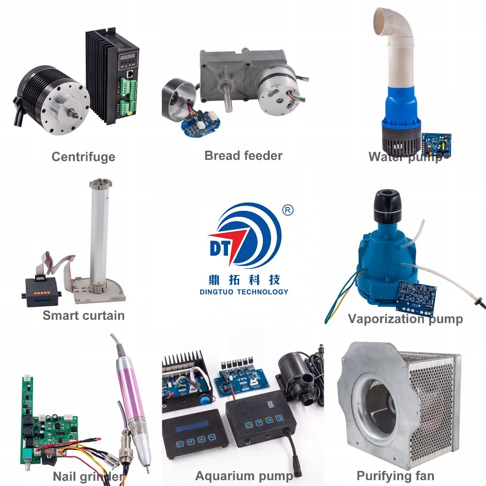
Customized Application Case

Certificates

As CE, ROHS, National Hi-tech Enterprise certified quality company, we strictly abide by Quality Control System, pursuing continuous improvement of products quality.
CE Declaration
DINGTUO' assures that our drives/motors meet the European Norm Standard.
RoHS Compliant
DINGTUO' is committed to offering products compliant with the EU RoHS directive.

National Hi-tech Enterprise
DINGTUO continues to carry out research and development and transformation of technological achievements in the "High-tech Fields Supported by the State", and forms core intellectual property rights of the enterprise, and conducts business activities based on this.
Computer Software Copyright Registration
DINGTUO obtained the computer software copyright registration certificate issued by the Copyright Bureau to realize the protection of computer software developed independently.

Customer Evaluation
Customer satisfaction is DINGTUO's primary aim, our drives and motors are designed to your exact specifications and we choose the right materials for client's samples.

Our Company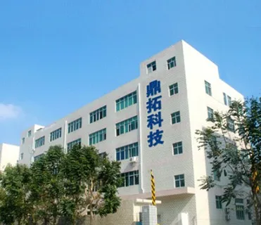
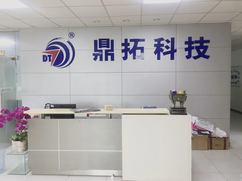
Who we are
Shenzhen Dingtuoda Electromechanics Co.,Ltd(DINGTUO TECHNOLOGY) was established in 2006. As a professional electric motor and driver manufacturer operating over 13 years, DINGTUO is first and foremost a reflection of its people.
Our company focus on professional R & D, production and sales of Servo/Stepper/BLDC motor system. We also committed to provide Customized OEM & ODM services to Global electrical distributors, industrial equipment manufacturers and automotive markets.
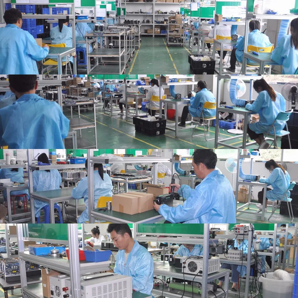
DINGTUO manufacturing center covering area around 2,500 M², and owning three production workshops, 9 production lines.
We are also continuously improving the performance and power efficiency of our products to help our customers enable new markets and applications.


Technology & Innovation
Manufacturing
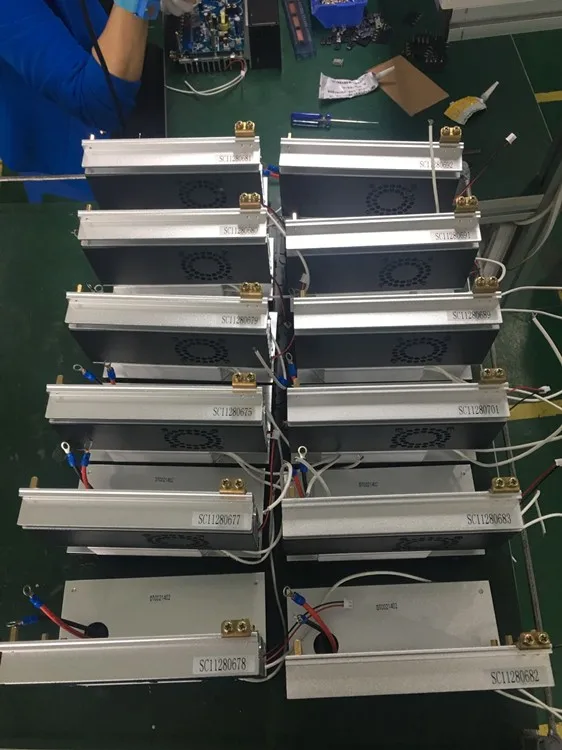
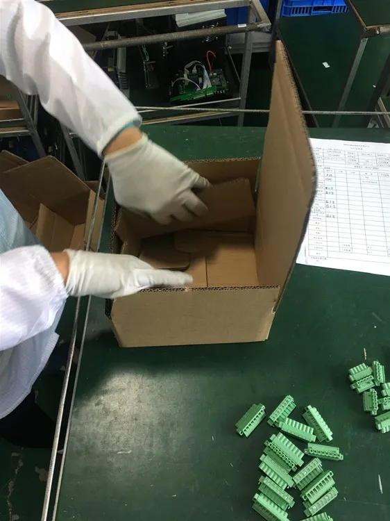
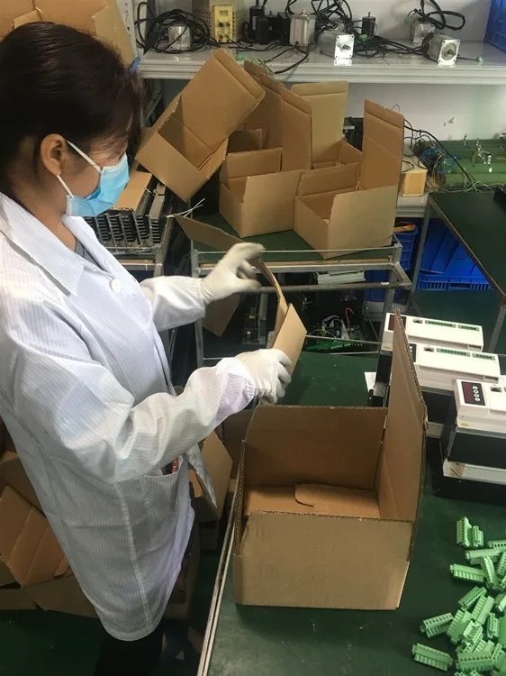
Quality and delivery are the most important aspects of DINGTUO Motor Driver's manufacturing processes. DINGTUO prides itself on offering the highest quality products with the best possible delivery times. It all begins with DINGTUO's manufacturing process. DINGTUO manufactures all of its products under strict quality standards at plants within Guangdong China.

Quality is Built-In
DINGTUO operates in a Just-in-time and a Lean Manufacturing environment. Quality is built-in to the product throughout the entire manufacturing process. This is achieved by utilizing the One-Piece Flow System on our Flexible U-line work cells wherein all necessary equipment are positioned in the sequence in which it is used. In the simplest of terms, one-piece flow means that each motor is carefully built one-piece-at-a-time allowing it to be thoroughly inspected and tested, thus, quality defects are easily detected and contained.
Additionally, defect prevention is also the direct result of the continuous error proofing of our processes.

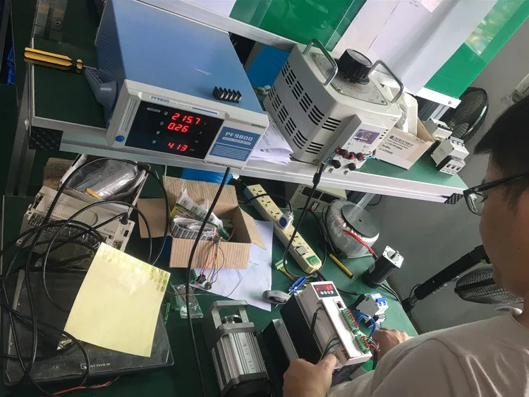
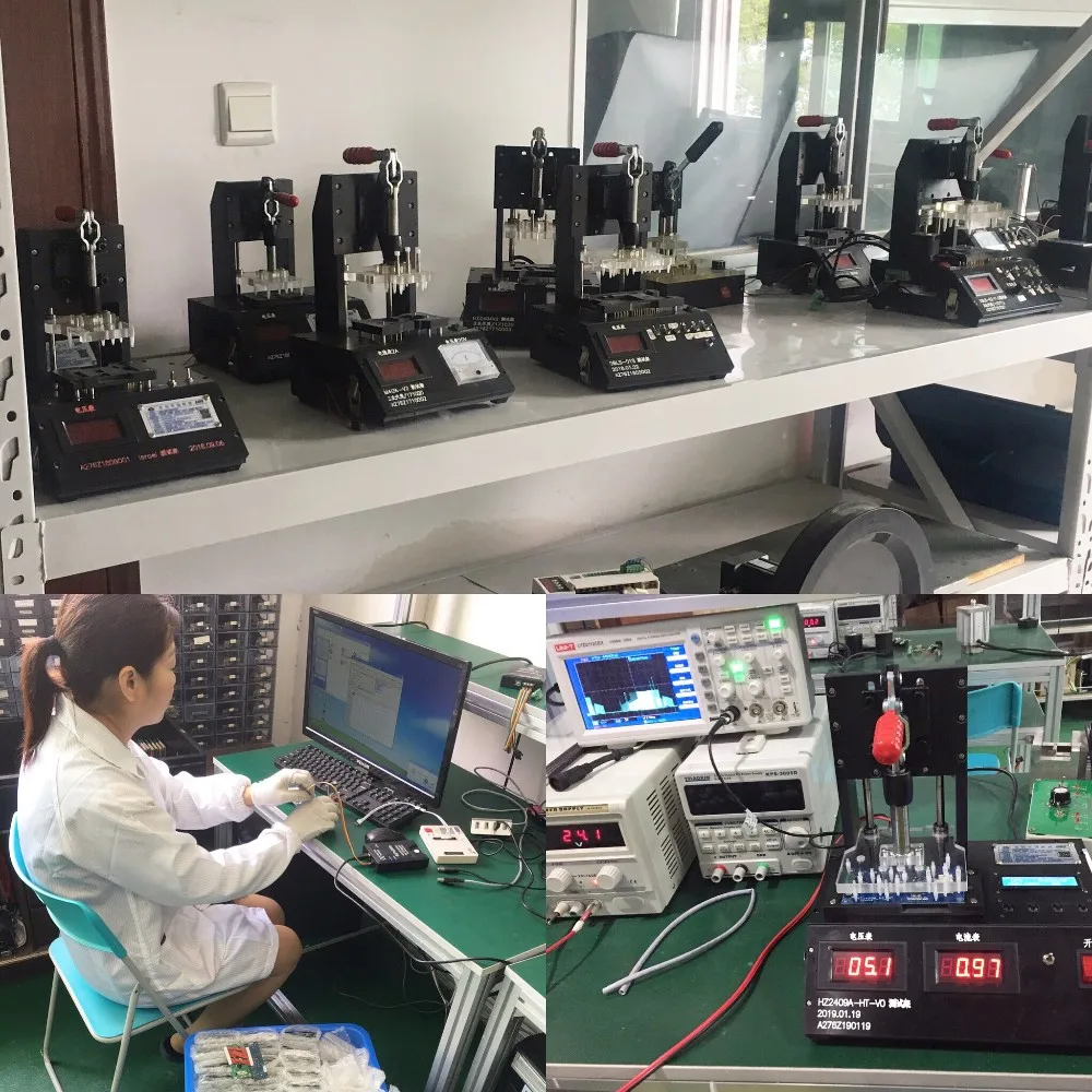
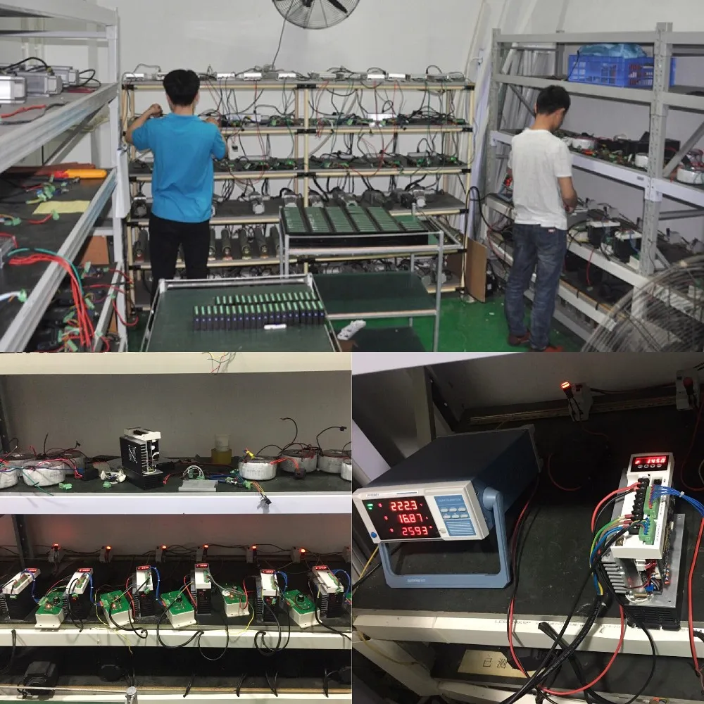
Product Testing
Every DINGTUO product undergoes reliability testing before they are released to the market. These test subject the product to the harshest of operating conditions and intentional misuse to discover the limits of their durability.

1 Year Warranty
DINGTUO stands behind every product with a 1 Year Warranty. Visit our warranty section for complete details.
Production Line
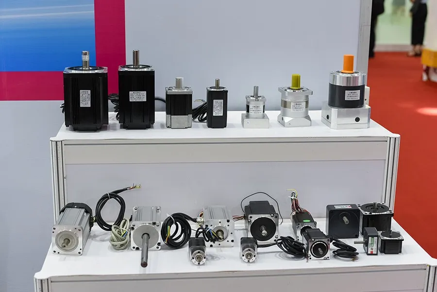
As the years of development, Now DINGTUO Technology has become the leader of motor control systems provider, It own production lines:
-Stepper Drives & Motors
-Servo Drives & Motors
-Brushless DC Drives & Motors
-Integrated Motors
-Linear Motion Systems


Advantage of DINGTUO TECHNOLOGY
-National High-tech enterprise certification
-Motor Drives Innovative &production team Over 13 years
-Electric Motor & Drives production workshop
-Strict quality management system
-Professional one stop supply & service
-OEM & ODM available
-Reliable and timely customer service
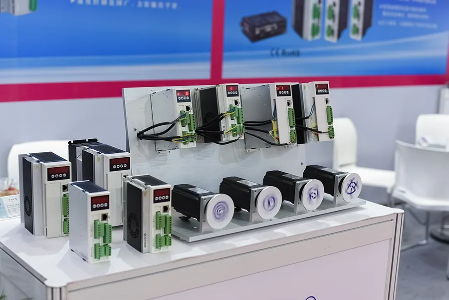
Trade Show
We Recommend


New Arrivals
New products from manufacturers at wholesale prices


