
Allosun EM2292 Tractor Unit Electrical System Tester 7 PIN
- Category: >>>
- Supplier: Zhangzhou Eastern Intelligent Meter Co. Ltd.
Share on (62089426214):
Product Overview
Description
Products Description
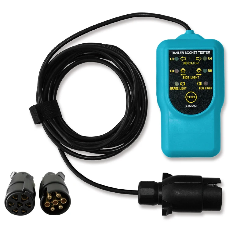
Tractor Unit Electrical System Tester
Instruction Sheet
The purpose of the tester is to test the trailer socket on the vehicle. With new
design, vehicle with a CAN-bus can also be tested. This tester is suitable only for 12V systems.
1. LED displays
When you turn on or activate a vehicle lamp, the vehicle’s wire connections for this lamp are good if the corresponding LED on the tester lights up; if the LED on the tester does not light up, the wire connections have fault.
table:The assignment of the LEDs on the tester is shown in the following
Pin Number | Wire Color | Wire for the following standard functions |
1 | RED | Left turn signal(green LED) |
2 | WHITE | Rear fog lamp(red LED) |
Ground | BLACK | If LED don't light, it may indicate problem in the ground |
4 | GREEN | Right turn signal (yellow LED) |
5 | YELLOW | Right tail light |
6 | BROWN | Brake lights |
7 | BLUE | Left tail light |
2. Connection
2.1 Insert the plug of the tester into the trailer socket on the vehicle, turn the vehicle’s power switch to the “ ON” position
but do not start the vehicle’s engine.
2.2 If the vehicle’s trailer socketis a 7-pole socket, insert the plug of the tester into the supplied adapter and then connect
the adapter to the 7-pole socket.
3. Testing the tail lamps, brake lamps and reversing lamp
3.1 To test these functions, switch on or activate the respective lamps.
If the corresponding LEDs on the tester light up, the vehicle’s wire connections for the lamps under test are good.
3.2 When the test finishes, switch off all the lamps.
4. Testing the flashers
4.1 Switch on or activate the left flasher. Then you can press the “L” end of Switch A to simulate a failure of the left flasher;
depending on the vehicle, this failure will be indicated in various ways, e.g. by a fault message on the vehicle’s instrument
panel.
4.2 Switch on or activate the right flasher. Then you can press the “R” end of Switch A to simulate a failure of the right
flasher; depending on the vehicle, this failure will be indicated in various ways, e.g. by a fault message on the vehicle’s
instrument panel.
5. Testing the hazard warning lamps
5.1 Switch on or activate the hazard warning lamps, press the “L+R” end of Switch B to simulate a failure of both flashers.
Depending on the vehicle, this failure will be indicated in various ways, e.g. by a fault message on the vehicle’s instrument
panel.
Failure identification is not possible through the flashing frequency of the flasher.
6. Testing the rear fog lamps
6.1 Switch on the rear fog lamp on the vehicle.
6.2 This light must not light up. If, nevertheless, it does, press the “54G” end of Switch B to switch it off.
7. Caution
To prevent the tester from overheating, do not press and hold down any switch of the tester for more than 15 seconds.
8. Technical data
Power Supply: 12V
Indicators: LEDs


Products Description
We Recommend


New Arrivals
New products from manufacturers at wholesale prices


