
DMA860H engraving machine driver 86 stepping motor driver DMA860H
US $12.00-$19.00
Share on (62089531267):
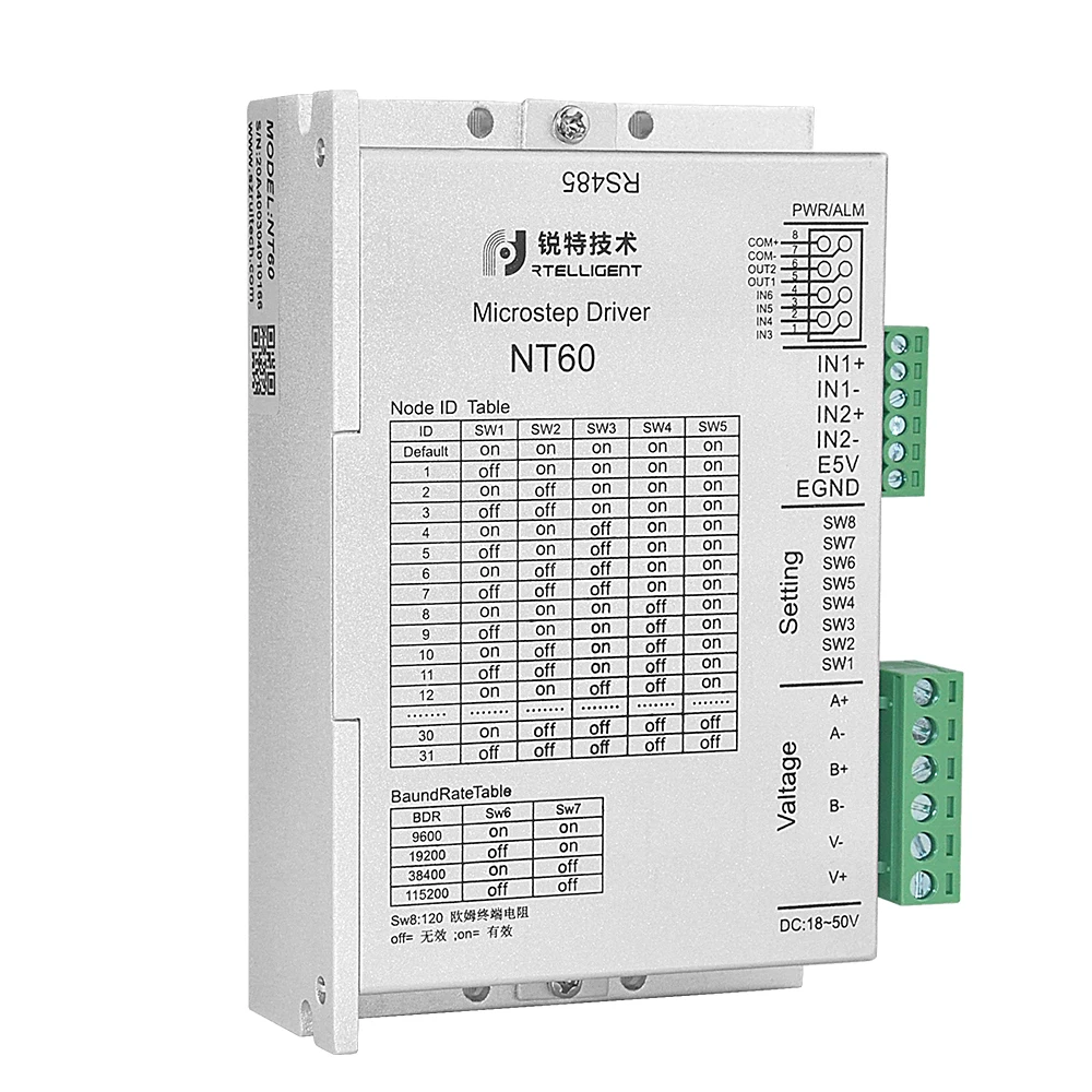
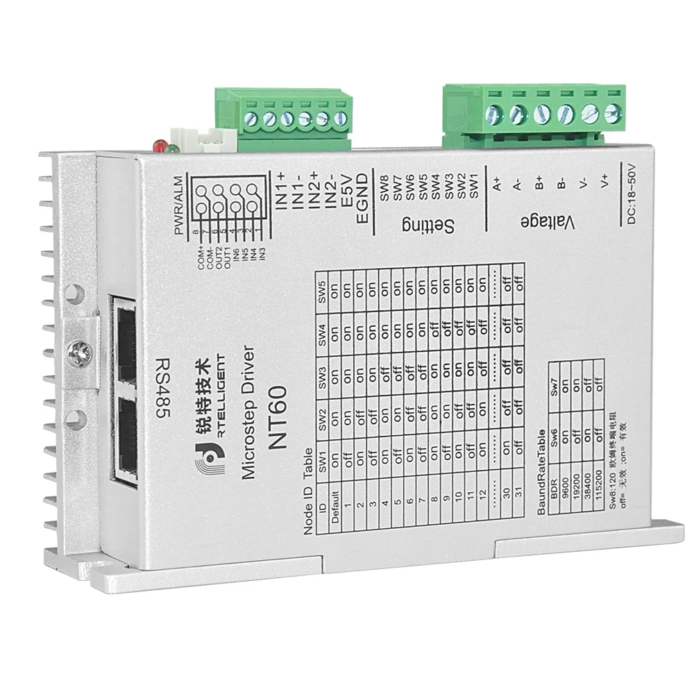
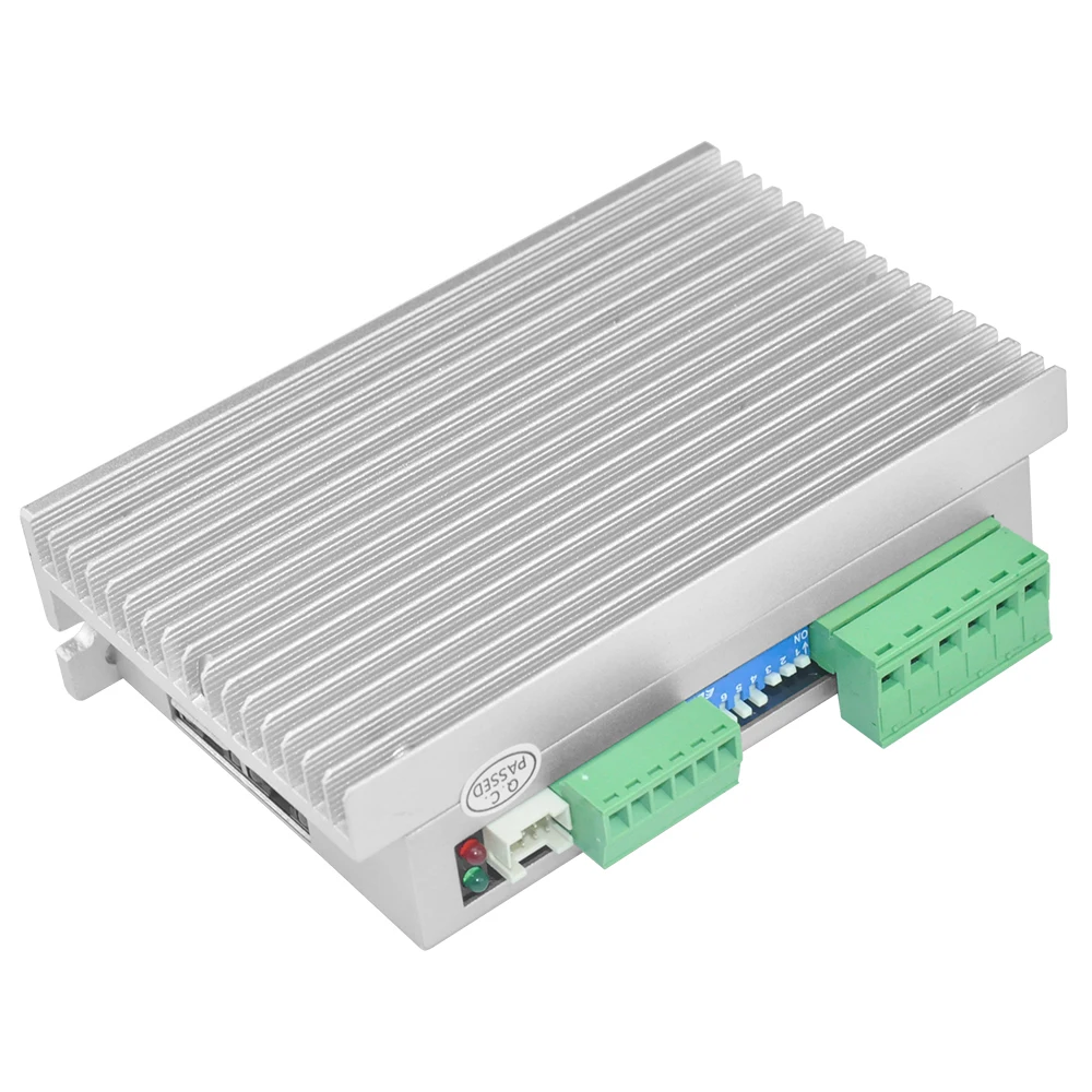
NT60 Bus stepper driver
NT60 designed by Rtelligent is a new high-performance 485 Bus control digital step motor drive which uses a 32-bit DSP processor. It also integrates an intelligent motion controller function with built-in S-shaped acceleration/deceleration commands to independently set acceleration and deceleration. The Modbus protocol is operated via the RS485 network to control the drive and motor in real time.
♦ Debugging software interface: USB to 485
♦ Maximum current : 5A
♦ Power supply : 24~50V DC; 36V or48V recommended
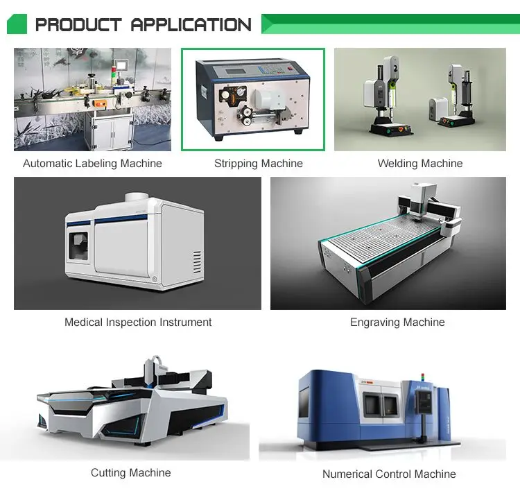
♦ Typical applications: assembly line, lithium battery equipment, solar equipment, 3C electronic equipment, etc.
| Function | Description of operations |
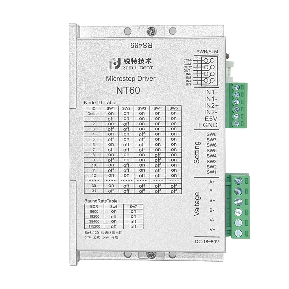
| Slave address setting | SW1-SW5,the five DIP switches, are used to set 32-bit DSP addresses in total. Please select the corresponding position according to the drive panel. |
| Baud rate setting | SW6-SW7, the two DIP switches, are used to select a total of 4 baud rates in total. The master and slave must be set to the same baud rate. Please selectthe corresponding position according to the drive panel. |
| Terminal matching resistor | sw8 is used to select whether the 120 ohm terminating resistor is valid, off is invalid, and on is valid. |
| CN interface | 4 single-ended input ports, 2 output ports, please see the table below for details. |
| Encoder interface | GND : Internal power supply output GND; +5 V : Internal power supply output 5V. When operating in the closed-loop mode, 5V power is supplied to the encoder. The maximum output current of this 5v signal should not exceed 150mA.IN2-, IN2+ : The differential input signal, the 5v level signal, can receive the pulse signal when the external pulse is open loop, and the quadrature encoder A phase signal in the closed loop mode. IN1-, IN1+ : Receives the quadrature encoder B-phase signal as the IN2 port. |
| Power and Motor interface | V-, V+ is powered by DC power supply. 24 - 50V DC is recommended for the operating voltage range, the power supply is greater than 150W. A+, A-, B-, and B+ are respectively connected to the A and B phase windings of the two-phase motor. |
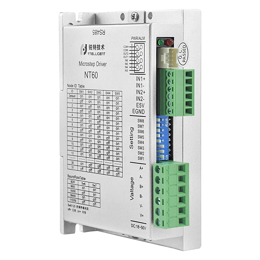
| Indicator | The drive has two indicators: the green one, a power indicator and twinkle upon the power up of drive; the red one, a fault indicator and twinkle in case of overvoltage and overcurrent. The red indicator goes off only when the fault is removed. The fault of drive can only be removed when the drive is powered on and enabled again. |
| RJ45 interface | Network communication interface, also used to connect PC debugging software. |


Any questions, feel free to contact me.
Company website: https://rtelligent.en.alibaba.com/?spm=a2700.icbuShop.88.22.512e44eeyrfOZV


New products from manufacturers at wholesale prices


