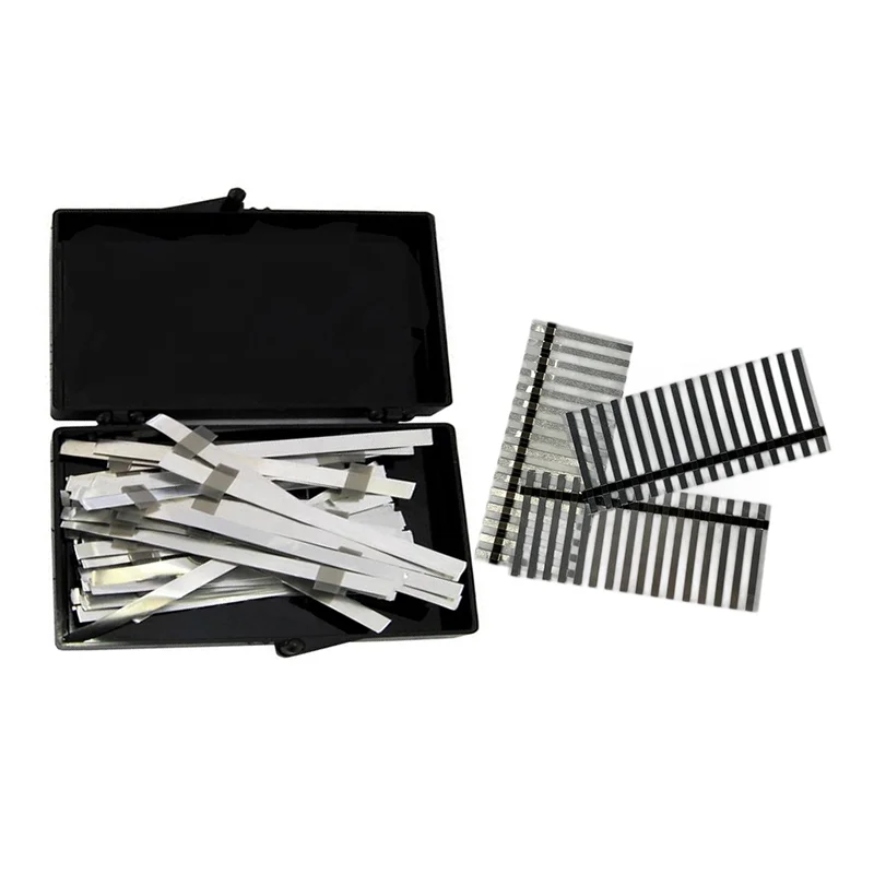
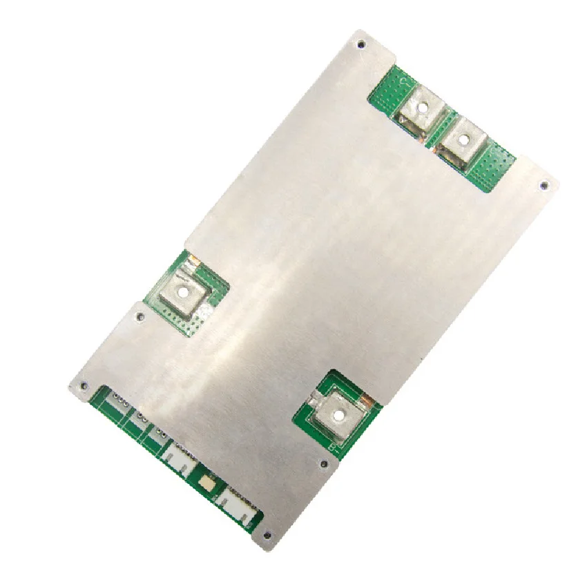
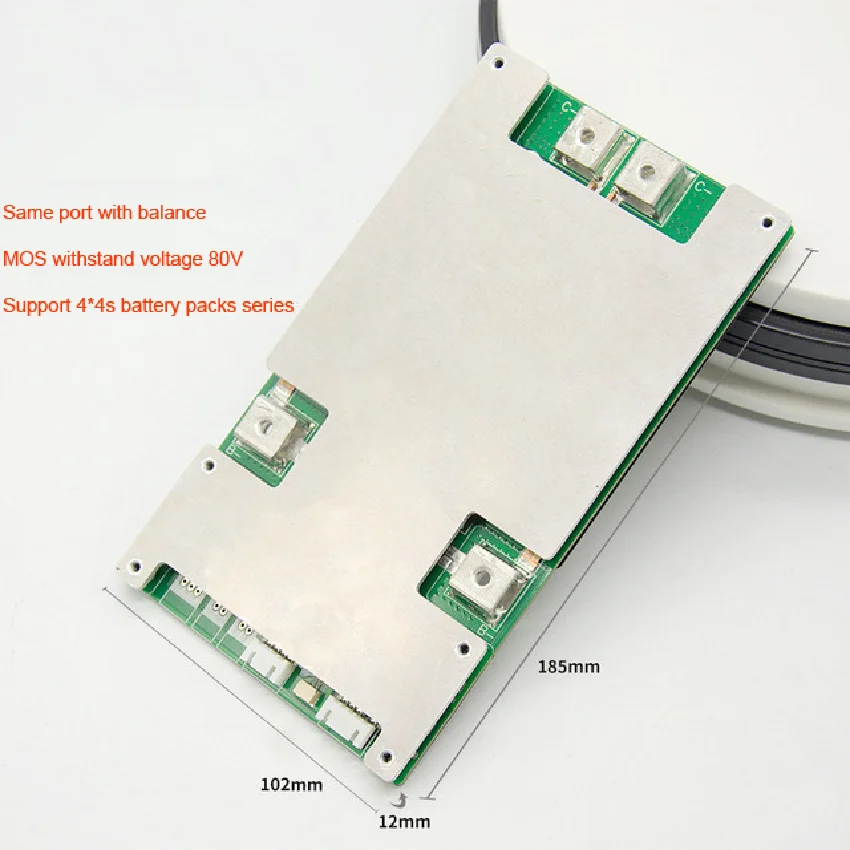
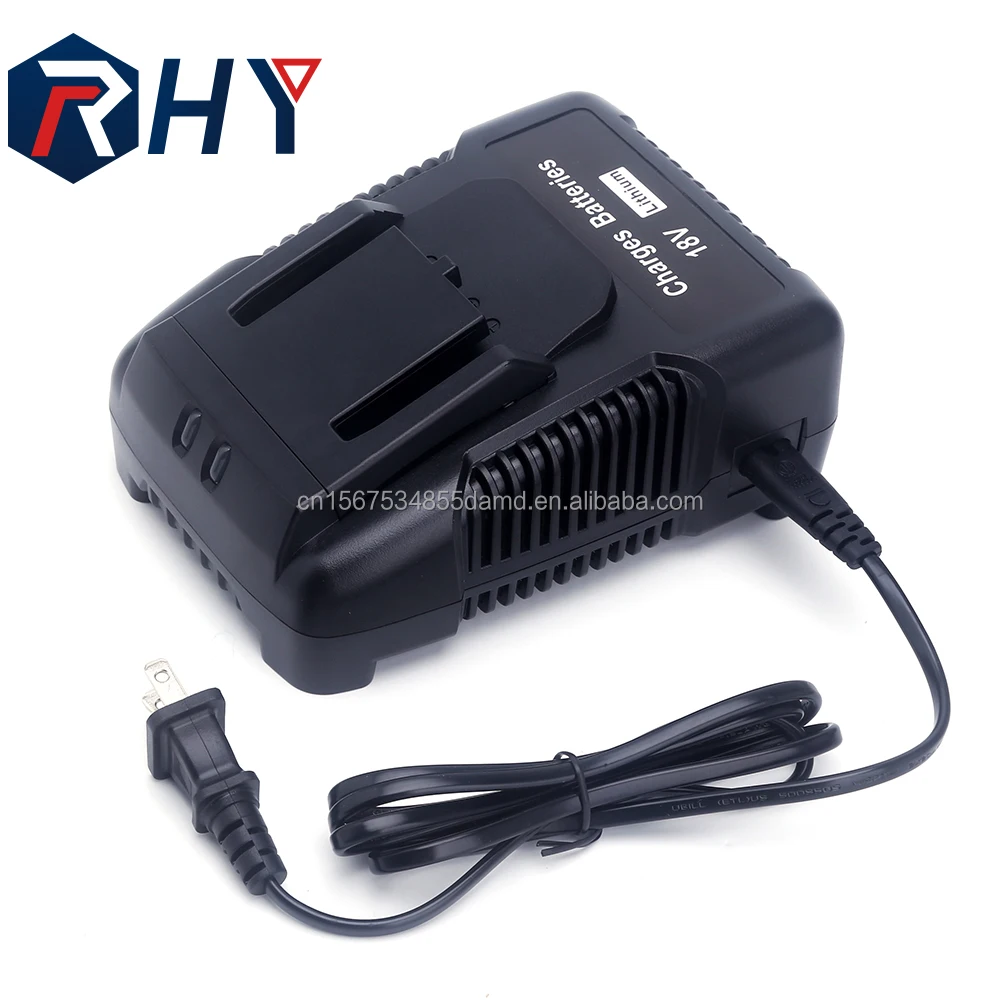
BT BMS lifepo4 bms 12v 4s 60A 80A 100A 120a 150A smart bms lithium iron phosphate battery PCM/PCBA
- Category: >>>
- Supplier: Shenzhen E-Fire Technology Development Co. Limited
Share on (62502689287):
Product Overview
Description
Product Description
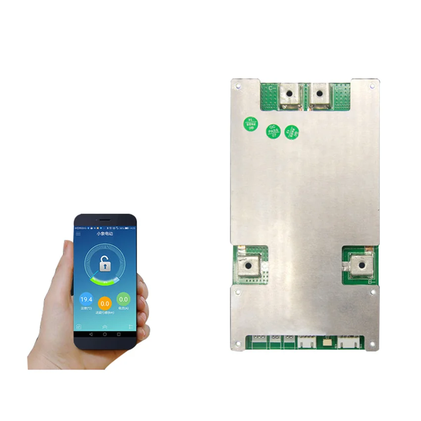
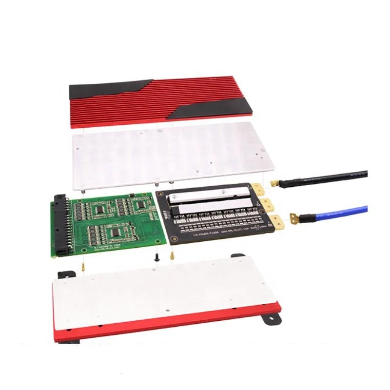
BT BMS lifepo4 bms 12v 4s 60A 80A 100A 120a 150A smart bms lithium iron phosphate battery PCM/PCBA
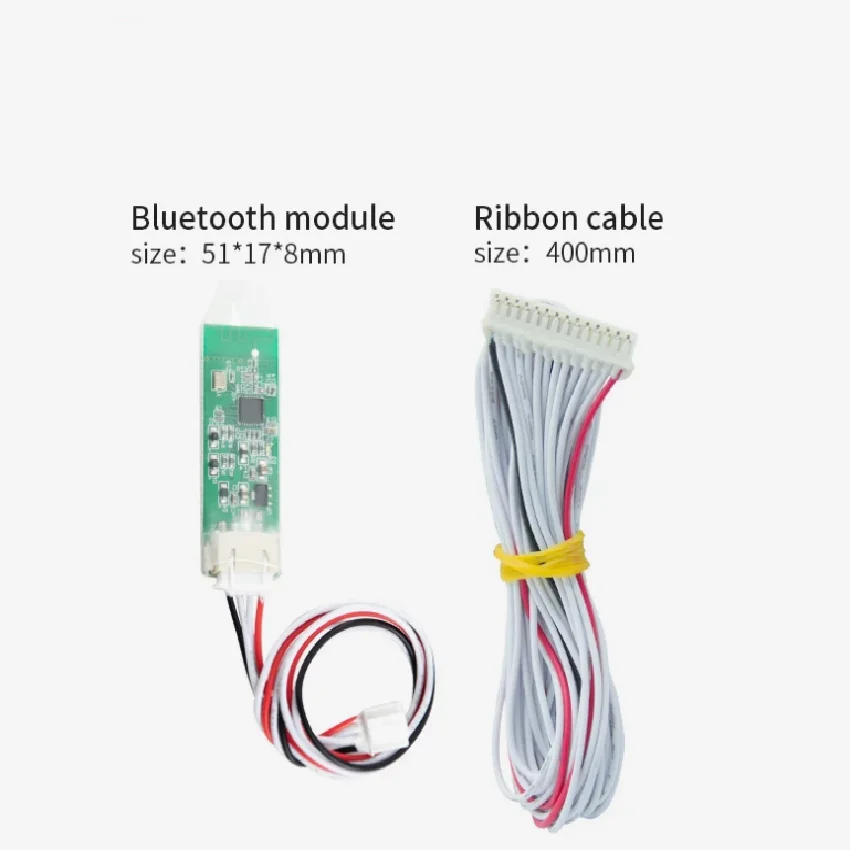
What BT Communication Module can do ?
With BT Communication Module , the APP Software can be connected , and all information of the BMS can display on your
Mobile Phone . and you can set some parameters on Your APP software :Over-protection voltage , Over-discharge protection voltage ,
Release voltage of over-charge and discharge
Adjustable BMS can set up Voltage and Current
You could get the SOC, RM, RSOC, Voltage, Current, Temperature of battery pack through UART connect
Please contact with us for more information
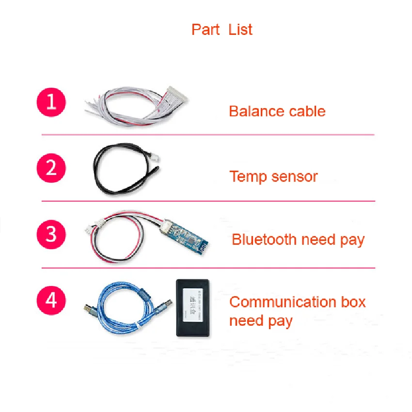
BT module is 6USD per pcs ,UART tool box is 8USD per pcs
If you buy our smart bms, we will offer you free software to download for cell phone and PC
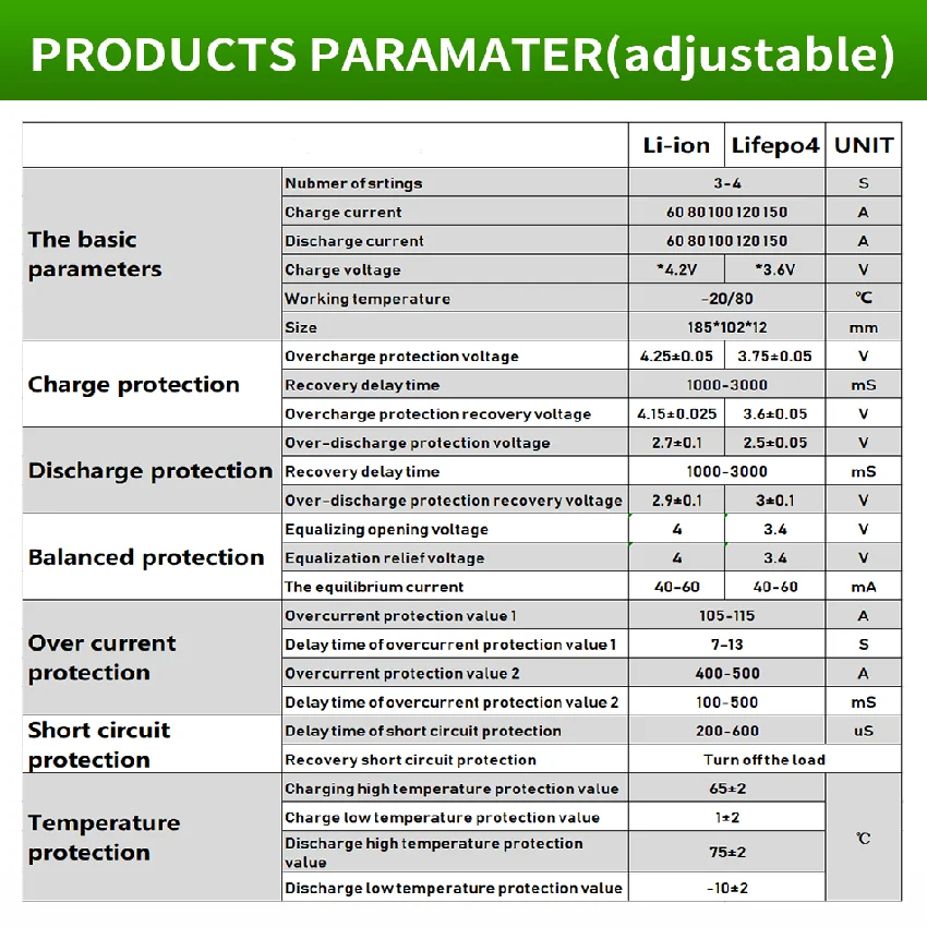
Items | Min. | Max. | Unit | Description |
Working humidity | -20 | +70 | ℃ | Normal working temperature range |
Storage temperature | -40 | +85 | ℃ | Humidity |
Functions | Test items | Specification | ||||||
Min. | Middle | Max. | Unit | |||||
Working Voltage | 10 | 14.6 | V | |||||
Working Current | Charge Current | 100 | 120 | A | ||||
Discharge Current | 100 | 120 | A | |||||
Charging protection | Charger voltage(CC-CV) lifepo4 | 14.6 | V | |||||
Charger voltage(CC-CV) Li-ion | Battery series *4.2 | V | ||||||
Over-charge protection voltage lifepo4 | 3.6 | 3.65 | 3.7 | V | ||||
Over-charge protection delay time | 1000 | 2000 | 3000 | mS | ||||
Over-charge protection recovery voltage lifepo4 | 3.45 | 3.5 | 3.55 | V | ||||
Discharge protection | Over-discharge protection voltage lifepo4 | 2.45 | 2.5 | 2.55 | V | |||
Over-discharge protection voltage | 1000 | 2000 | 3000 | mS | ||||
Over-discharge protection recovery voltage lifepo4 | 2.9 | 3 | 3.1 | V | ||||
Overcurrent protection | Charge Over Current | 120 | 130 | 140 | A | |||
Charge Over Current Delay Time | 1 | 2 | 3 | S | ||||
Over Current Release Condition | 32 | S | ||||||
Discharge overcurrent 1 protection current value | 120 | 130 | 140 | A | ||||
Discharge overcurrent 1 protection delay | 1 | 3 | S | |||||
Discharge overcurrent 2 protection current value | 360 | 400 | 420 | A | ||||
Discharge overcurrent 2 protection delay | 100 | 500 | mS | |||||
Discharge overcurrent protection recovery condition | 32 | S | ||||||
Short circuit protection | Short circuit protection delay time | 200 | 500 | uS | ||||
Short Circuit Release | Disconnect the load | |||||||
Balanced function | Balanced turn-on voltage lifepo4 | 3.35 | 3.4 | 3.45 | V | |||
V | ||||||||
Voltage difference achieves the starting condition | 30 | mV | ||||||
balanced pattern | charge balance | |||||||
Balanced current | 40 | 60 | mA | |||||
Temperature protection | High temperature protection for charging | 63 | 65 | 67 | ℃ | |||
Release value of charging high temperature protection | 53 | 55 | 57 | ℃ | ||||
Low temperature protection for charging | -2 | -1 | 0 | ℃ | ||||
Discharge high temperature protection value | 68 | 70 | 72 | ℃ | ||||
Discharge high temperature protection release value | 58 | 60 | 62 | ℃ | ||||
Discharge low temperature protection value | -12 | -10 | -8 | ℃ | ||||
Discharge value at low temperature | -2 | 0 | 2 | ℃ | ||||
Internal resistance | Discharge loop internal resistance | / | 5 | 10 | mR | |||
Self-consuming | Operating mode | 20 | mA | |||||
Sleep mode | 200 | uA | ||||||
Sleep delay | no electricit/no communication line/Delay in unprotected state 10s | |||||||


Warning :
1,Should strictly follow the connection step as the diagram.
2,Double check the connection is correct,then connect it to the battery pack "+","-" Pin.
3,We are not responsible for the defectives caused by wrong connection.
Trust me, if the wiring is correct, the defect rate is 0.
1,Should strictly follow the connection step as the diagram.
2,Double check the connection is correct,then connect it to the battery pack "+","-" Pin.
3,We are not responsible for the defectives caused by wrong connection.
Trust me, if the wiring is correct, the defect rate is 0.
FAQ
FAQ
1.What is the common port and separate port? what is the difference?
We take 13S48V16A BMS as an example, common port 16A means your charge cathode and discharge cathode are connected in the same point end(our P-), charge cathode and discharge cathode are used in the common connection port, so the charge current and discharge current are the same 16A. while the separate port is separately connected by charge cathode (C-) and discharge cathode (P-), so the charge current and discharge current are different, discharge current 16A, charge current 8A.
2.What is the balance function?
The working principle and function are as followings, when your one cell voltage is up to alarm voltage(Li-ion up to 4.18V, Life Po4 up to (3.6V), then the cell Balance starts to work, balance resistance starts discharge with 35ma(when balance discharge starts to work, BMS will starts a little heat up, which is the normal reflection), the cell is in both charging and discharging status, and others which are not reached to alarm voltage(Li-ion 4.18V, Life Po4 3.6V) are only in charging status, no discharging, when the fast cell voltage is reached to alarm voltage(Li-ion 4.25V, Life Po4 3.75V)BMS starts off power protection, all the other cells are all in stop of charging, this process will enable your battery charging in balance current, and your battery voltage are in balance status, but when your cell voltage difference are in a big range, then balance can not be functioning well .
3.The relationship between Battery capacity and BMS current?
There is no direct relationship between Battery capacity and BMS current, big capacity doesn’t mean a big battery, but rely on continue current, that is to say if your engine is powerful, your should choose high current of BMS, it is not relied on battery capacity.
4. What type of charger should I choose?
Lithium battery must choose specific charger, do not use Charger for Lead acid battery, for lead acid charger may have MOS with high pressure breakdown protection, which will not protect of BMS over charge.Life Po4 battery charger voltage=battery string No.X3.6V, while Li-ion battery charger voltage=Battery string No.X4.2V.
5. What current BMS should I choose ?
Take 10S36V as an example: what current BMS you choose is relied on your E-bicycle Motor power and current limitation of controller. eg., choose 16A for below 350W, 25A for below500W, 35A for below 800W, 60A for Below 1000W, higher than 1200W are contact with our service specialist for suggestions, one in all, continue current shall be higher than current limitation in Controller.
6. Whether my BMS damaged?
if you want to judge if the BMS is damaged, please take the following steps, to test if each cell voltage is the same with voltmeter? if the cell voltage difference is over 1.0V, the fault is displayed that it cannot run far, no power supply at the start range, short charge time, all these issues are almost caused by battery cells, if BMS damaged is displayed as no charge, no discharge, no discharge while the battery has voltage.
Attention When Connecting:
When we connect BMS with cells or disassemble BMS from battery pack, the following order and regulations must be complied with to avoid damage of components of BMS and problems of not protecting of cells.
In order to achieve the best performance of BMS and to run the longest distance, all the battery must be matched well (Each battery voltage difference less than 0.05V, IR difference less than 15 mΩ, capacity differenace less than 30mAh) to make sure the better consistency of the battery.
Cell must be connected in parallel first, after then connected in series.
Connection:
1. Connect charging /discharging wire, battery pack negative wire.
2. After confirm the wires are connected OK, plug the connector cable in the BMS
Do not plug connector cable in the BMS before connect wire.
Attention, ESD protection during work.
We Recommend

New Arrivals
New products from manufacturers at wholesale prices


