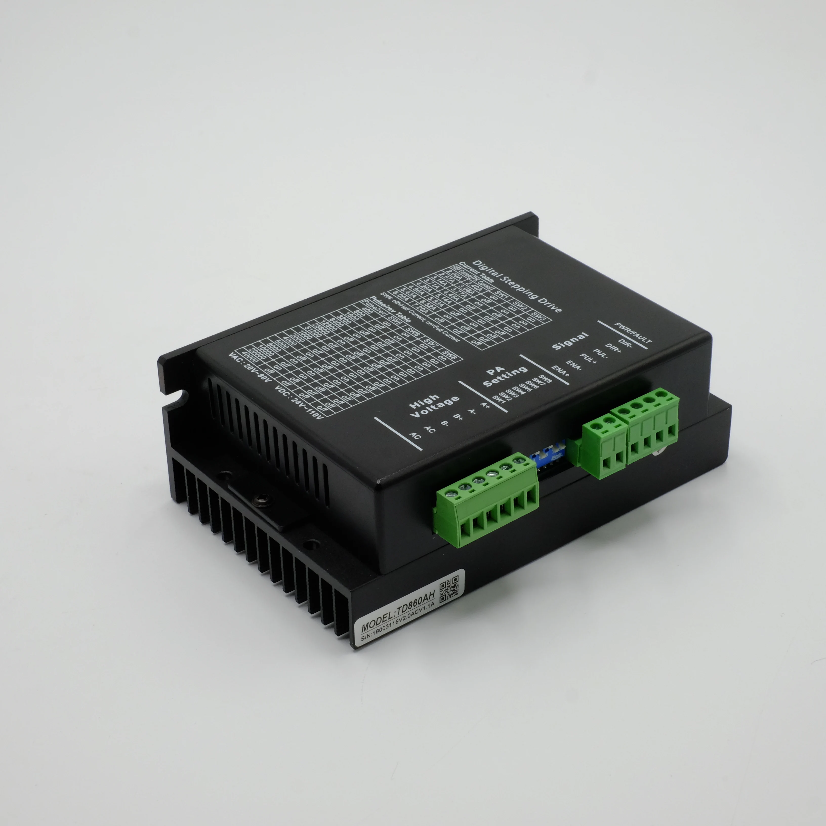
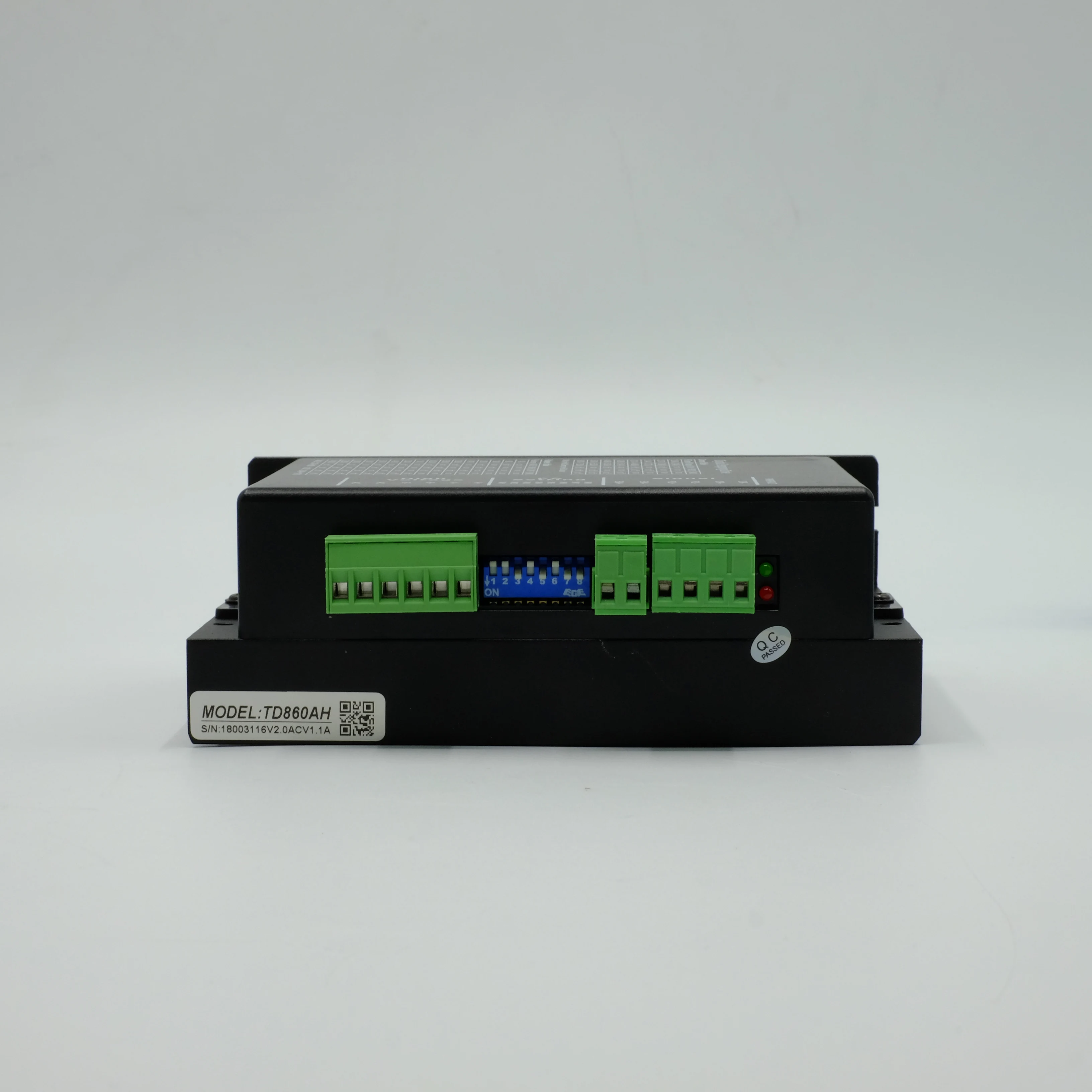
Цифровой шаговый привод TD860AH 2 фазный мотор драйвер переменного тока/DC привода
- Категория: Motor Drivers >>>
- Поставщик: Shenzhen Kaxingtong Technology Co. Ltd.
Сохранить в закладки 1600115649182:
Описание и отзывы
Характеристики
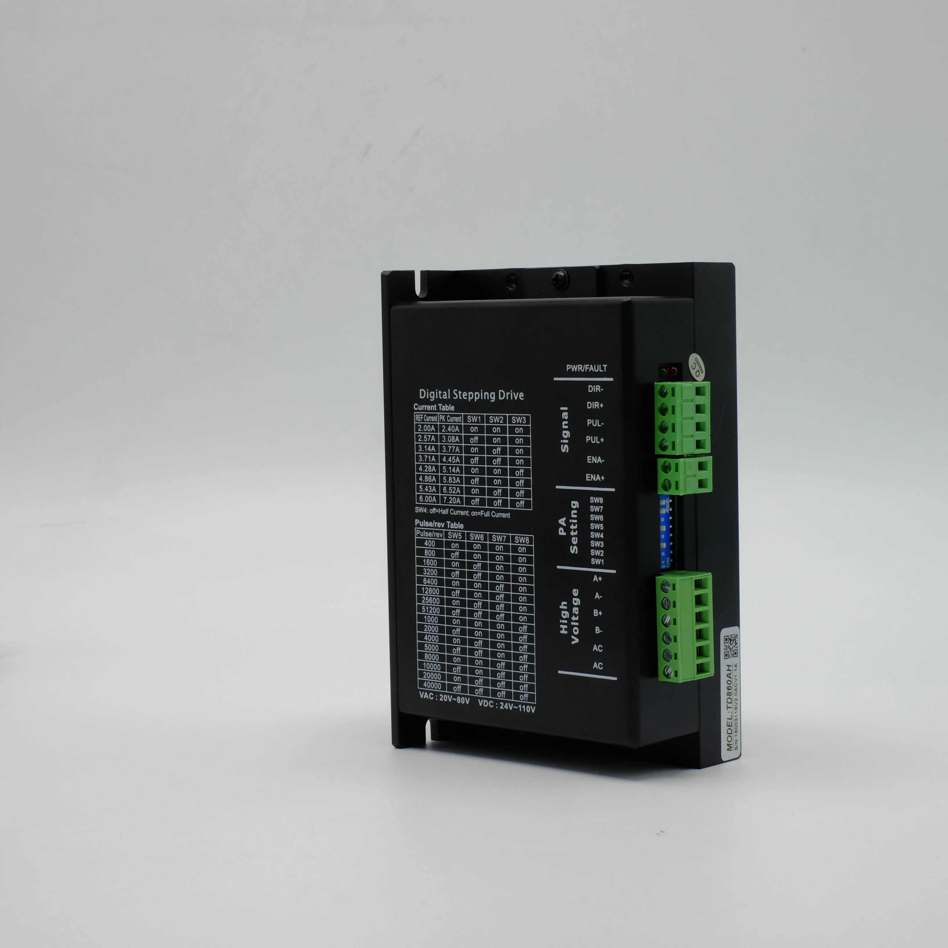
The TD860AH is a versatility fully digital stepping Drive based on a DSP with advanced control algorithm. The TD860AH is the next generation of digital stepping motor controls. It brings a unique level of system smoothness, providing optimum torque and nulls mid-range instability. Motor self-test and parameter auto-setup technology offers optimum responses with different motors and easy-to-use. The Drive motors can run with much smaller noise, lower heating, smoother movement than most of the Drives in the markets. Its unique features make the TD860AH an ideal solution for applications that require low-speed smoothness.
Compared to the DM860, broader input voltage and output current ranges make the TD860AH can Drive much more motors than the DM860. What’s more, owing to its higher performance DSP, Drive motors can achieve much higher speed (above 3000RPM) than that of the DM860,offering servo-like performances.
1.2 Features
l Anti-Resonance, provides optimum torque and nulls mid-range instability
l Motor self-test and parameter auto-setup
technology, offers optimum responses with
different motors
l Multi-Stepping allows a low resolution step
input to produce a higher microstep output
for smooth system performance
l Microstep resolutions programmable, from full-step to 102,400 steps/rev
l Supply voltage up to 75 VAC/+110VDC
l Output current programmable, from 0.5A to
7.2A
l Pulse input frequency up to 200 KHz
l TTL compatible and optically isolated input
l Automatic idle-current reduction
l Suitable for 2-phase and 4-phase motors
l Support PUL/DIR and CW/CCW modes
l Over-voltage, over-current, phase-error protections
1.3 Applications
Suitable for a wide range of stepping motors, from NEMA frame size 17 to 34. It can be used in various kinds of machines, such as laser cutters, laser markers, high precision X-Y tables, labeling machines, and so on. Its unique features make the TD860AH an ideal solution for applications that require both low-speed smoothness and high speed performances.
2,Specifications
2.1 Electrical Specifications (Tj = 25℃/77℉)
Parameters | TD860AH | |||
Min | Typical | Max | Unit | |
Output current[PK] | 0.5 | - | 7.2(6.0 RMS) | A |
Supply voltage | 24 | 48 | 75 | Vac |
Pulse Voltage | 4 | 5 | 28 | Vdc |
Logic signal current | 7 | 10 | 16 | mA |
Pulse input frequency | 0 | - | 200 | KHz |
Isolation resistance | 100 | - | - | MΩ |
2.2 Mechanical Specifications (unit: mm)
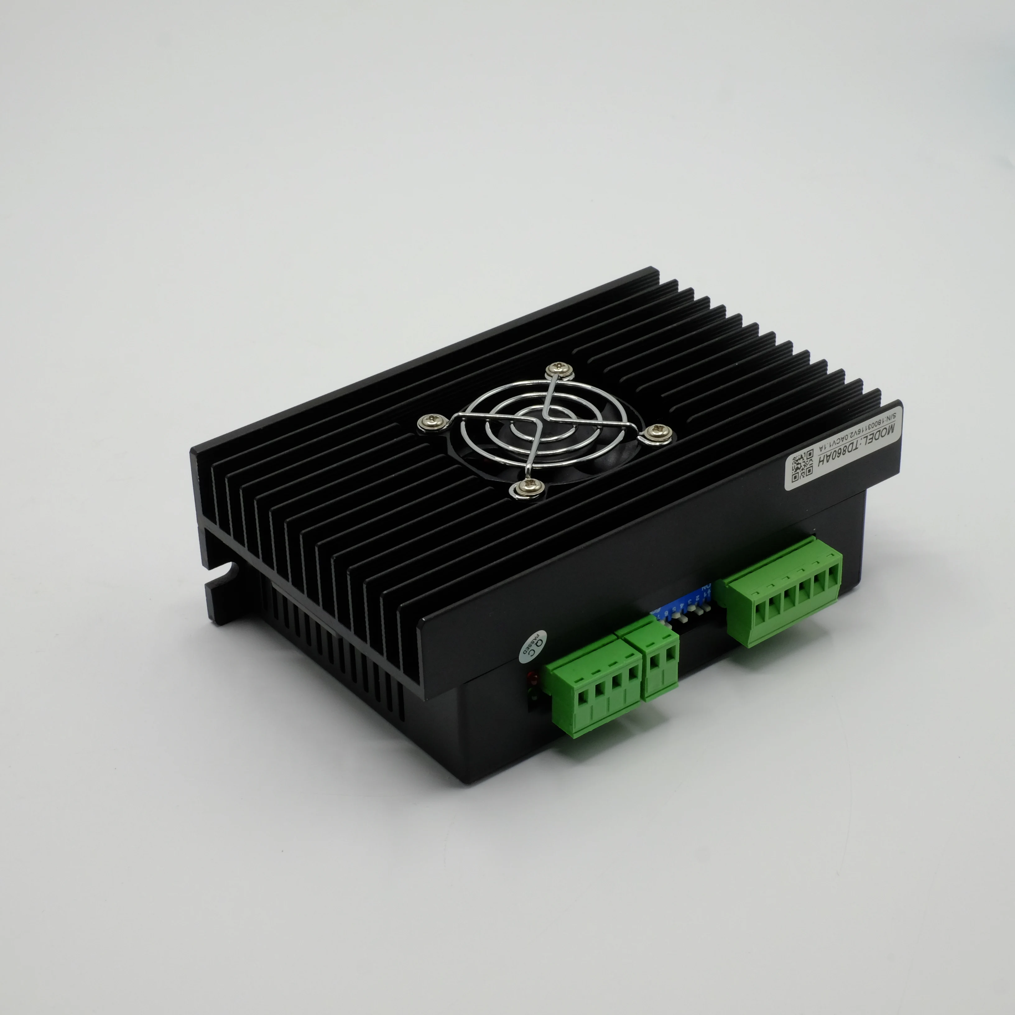
2.3 Elimination of Heat
l Drive’s reliable working temperature should be <70℃(158℉), and motor working temperature should be <80℃(176℉);
l It is recommended to use automatic idle-current mode, namely current automatically reduce to 60% when motor stops, so as to reduce Drive heating and motor heating;
The Drive must be mounted vertically to maximize heat sink area as shown in the following
picture. Use forced cooling method to cool the system if necessary.
2.4 Operating Environment and other Specifications
Cooling | Natural Cooling or Forced cooling | |
Operating Environment | Environment | Avoid dust, oil fog and corrosive gases |
Ambient Temperature | 0℃ -50℃ (32℉ -122℉) | |
Humidity | 40%RH -90%RH | |
Operating Temperature | 70℃ (158℉) Max | |
Storage Temperature | -20 ℃ - 65℃ (-4℉ - 149℉) | |
Weight | Approx. 280g (10 oz) | |
3. Pin Assignment and Description
The TD860AH has two connectors, connector P1 for control signals connections, and connector P2 for power and motor connections. The following tables are brief descriptions of the two connectors. More detailed descriptions of the pins and related issues are presented in section 4, 5, 9.
3.1 Connector P1 Configurations
Pin Function | Details |
PUL+ | Pulse signal: In single pulse (pulse/direction) mode, this input represents pulse signal,active at each rising or falling edge (software configurable). In double pulse mode (software configurable), this input represents clockwise (CW) pulse, active both at each high level and low level. 4-28V for PUL-HIGH, 0-0.5V for PUL-LOW. For reliable response,pulse width should be longer than 2.5μs for 200K MAX input frequency or 1μs for 500K MAX input frequency. |
PUL- | |
DIR+ | Dir signal: In single-pulse mode, this signal has low/high voltage levels,representing two directions of motor rotation; in double-pulse mode (software configurable), this signal is counter-clock (CCW) pulse,active both at high level and low level (software configurable). For reliable motion response, DIR signal should be ahead of PUL signal by 2.5μs at least. 4-28V when DIR-HIGH,0-0.5V when DIR-LOW. Please note that rotation direction is also related to motor-Drive wiring match. Exchanging the connection of two wires for a coil to the Drive will reverse motion direction. |
DIR- | |
ENA+ | Enable signal: This signal is used for enabling/disabling the Drive. High level (NPN control signal, PNP and Differential control signals are on the contrary,namely Low level for enabling.) for enabling the Drive and low level for disabling the Drive. Usually left UNCONNECTED (ENABLED). |
ENA- |
3.2 Selecting Active Pulse Edge and Control Signal Mode
The TD860AH supports PUL/DIR and CW/CCW modes and pulse actives at rising or falling edge. See more information about these settings in Section 13. Default setting is PUL/DIR mode and rising edge active (NPN, and PNP control signal is on the contrary).
3.3 Connector P2 Configurations
Pin Function | Details |
AC | Power supply, 24~75 Vac or 24~110Vdc, Including voltage fluctuation and EMF voltage. |
AC | Power supply, 24~75 Vac or 24~110Vdc, Including voltage fluctuation and EMF voltage. |
A+,A- | Motor Phase A |
B+,B- | Motor Phase B |
Похожие товары
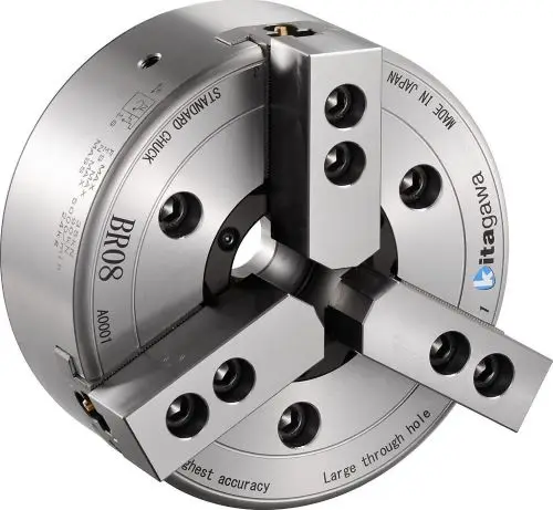
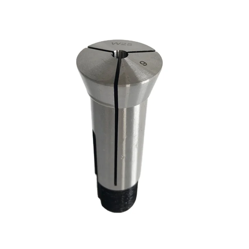
Высокое качество и надежность 6 Щековая токарный станок для Китагава патрон для промышленного использования
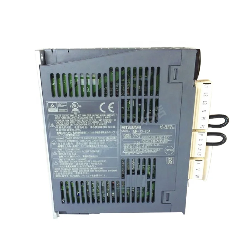
Горячая Распродажа Mitsubishi Серво привод MR-J3-60B с секундной стрелкой в наличии на складе
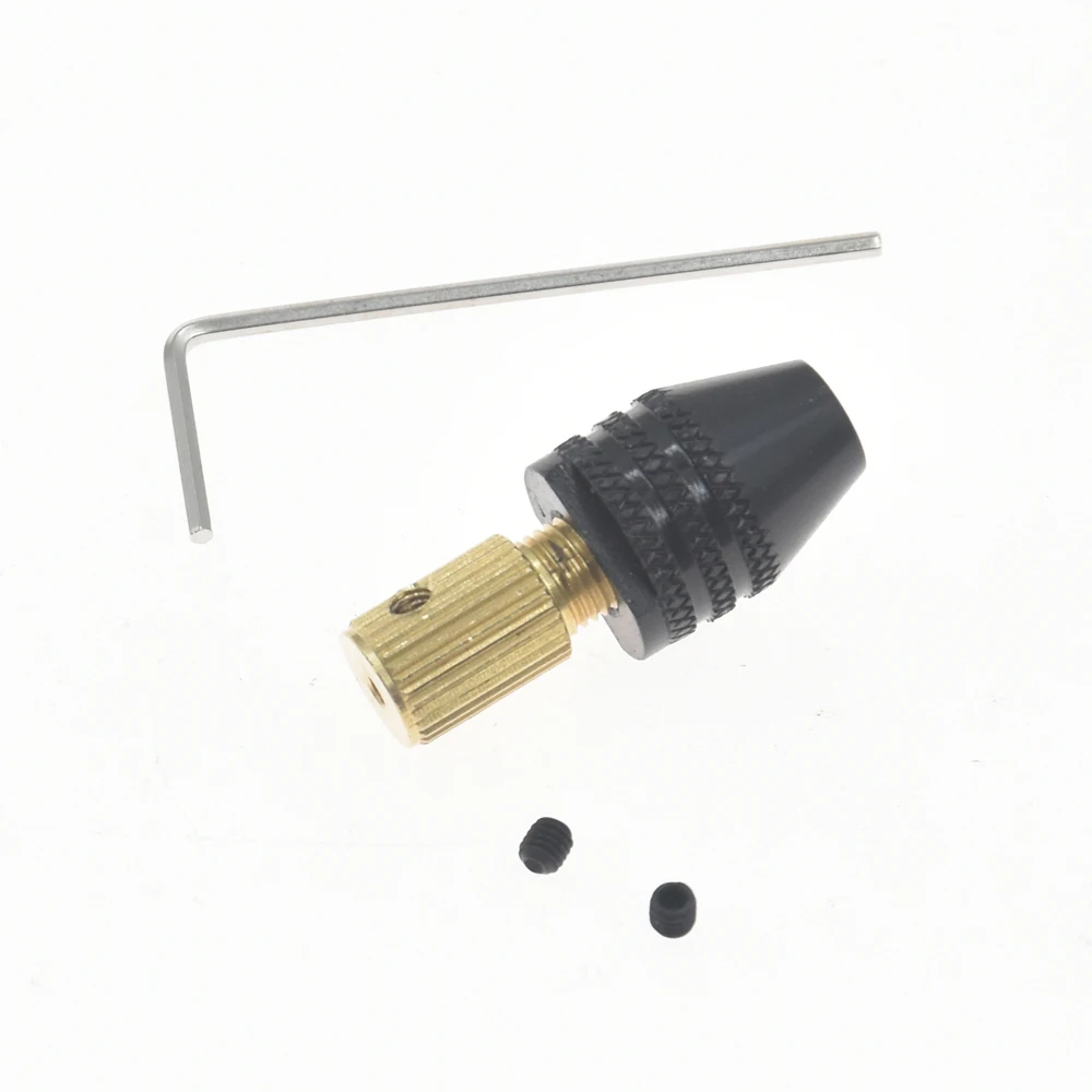
2,3 мм мини-патрон для электронной дрели диапазон 0,5-3,2 мм хвостовик Вал адаптер инструменты сверлильный патрон
1,23 $ - 2,15 $
Деревообрабатывающий грузовик патрон Зонт передач патрон Самоцентрирующийся зажимной древесины токарно-револьверный станок патрон
K11 серии 3 Щековая патроны токарные с Самоцентрирующийся для скамейке токарного станка
12-65 мм 3-кулачковый зажимного аксессуара с большой диапазон зажима для самостоятельной сборки мини токарные станки машина инструменты
Высокоточный БЕСКЛЮЧЕВОЙ сверлильный патрон 13 мм-B16 сверлильные патроны
8,66 $ - 10,60 $
Новые поступления
Новинки товаров от производителей по оптовым ценам
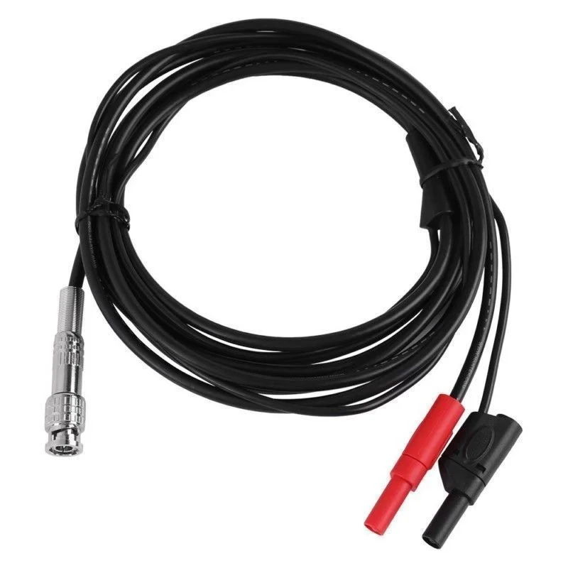
Hantek щупы осциллографа автоматический Тестовый Кабель Ht30a Bnc к банану двойная Банановая головка многоцелевое автомобильное
3,10-3,44 $

Горячая распродажа ручная работа традиционная деревянная урна для домашних животных квадратная коробка золы собак и кошек персонализированная Лучшая цена
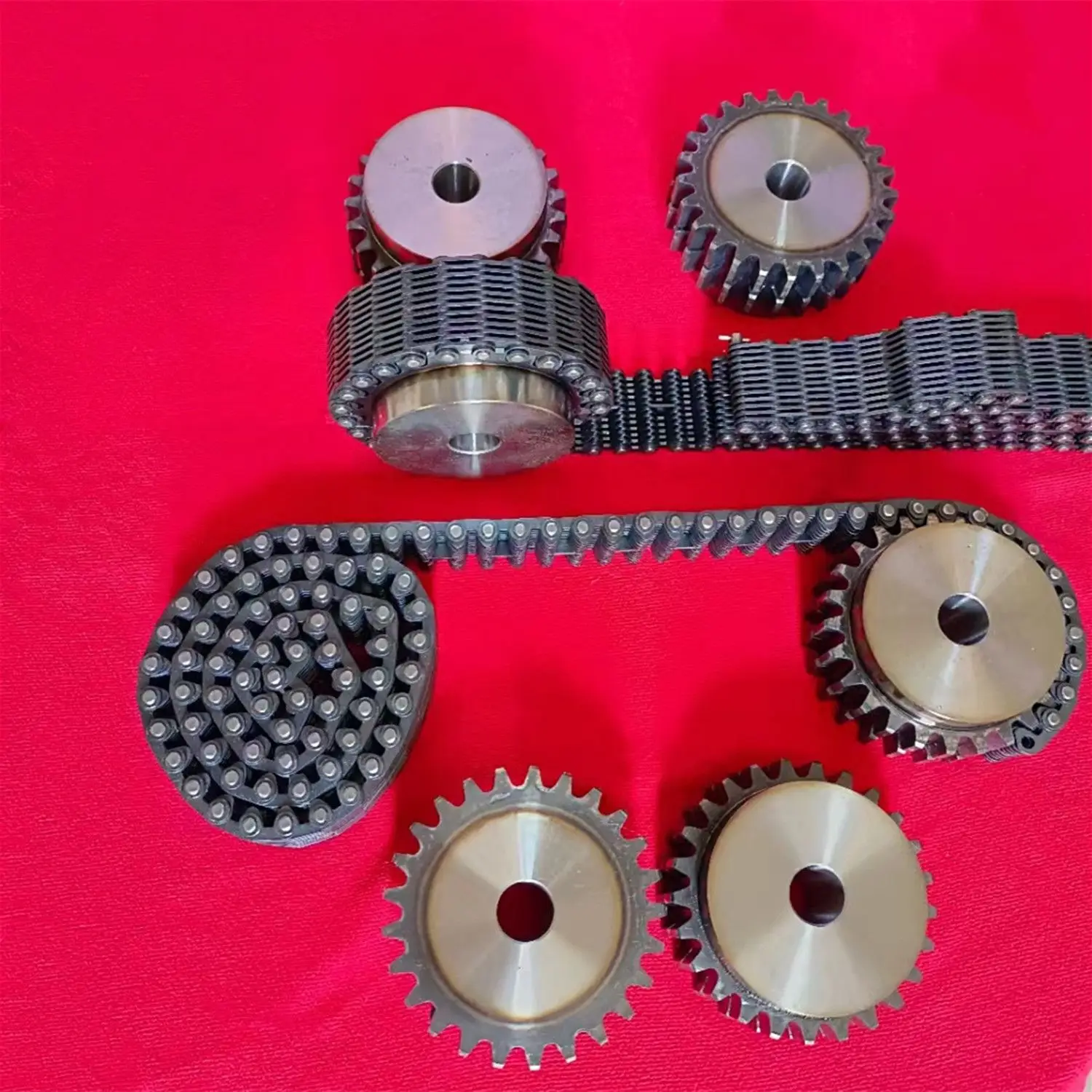
Промышленная серия CL Бесшумная цепь стальная зубчатая Фланцевая контактная звездочка соединяющая бесшумные цепи
1-1,50 $

Irdmco экологически чистый минималистичный прямоугольный деревянный ящик для хранения стеллаж поделок и детских игрушек Домашняя мебель гостиной

Технология сенсорных перчаток и аксессуары для детей от дождя холода M725132-334
1,07-1,40 $

GY6 6 Pin AC гоночный CDI для CG125 CG250 двигателя Dirt Pit Bike ATV Quad

Парик из синтетического волокна для косплея
9,85-12,66 $

Прямая Продажа с фабрики 65 см Модернизированный подвесный стерео голографический проектор светодиодный вентилятор высокой четкости экран 3D дисплей
155-185 $