NCS Series of Intelligent Transmitters are digital, intelligent, network-based, merged with advanced, reliable and stable sensor technology, to be designed as a new generation of Fieldbus Intelligent Transmitter. NCS Series of Intelligent Transmitter have been designed with high precision and high reliability, high stability. The pressure, temperature, currents and other physical quantities are displayed on LCD module. Zero drift, range settings and many other functions, are realized by the magnetism bar operation. The interoperability between different systems and equipments are realized by the Equipment Description Document, which is coMpatible to a variety of device management software, and adapting to harsh electromagnetic environment. NCS Series of Intelligent Transmitter have been used in inflammable and explosive places according to Intrinsically Safety Design. NCS-PT105 series of Intelligent Pressure Transmitters are well- designed with advanced, mature and reliable capacitance sensors, combined with advanced microprocessor technology and digital capacitance measurement technology. Internal microprocessor make it intelligent, high-precise, high reliable and zero-point stable. It is easy to debug in the field. |
According to the Type of Measurable Pressure:
Model |
Pressure Type |
NCS-PT105ⅡSG |
Gauge Pressure Transmitter |
NCS-PT105ⅡSA |
Absolute Pressure Transmitter |
NCS-PT105ⅡSD |
Differential Pressure Transmitter |
NCS-PT105ⅡSH |
Differential Pressure Transmitter For High Static Pressure |
According to the Protocol:
Model |
Communication Protocol Type |
NCS-PT105ⅡF |
FF H1 |
NCS-PT105ⅡP |
PROFIBUS PA |
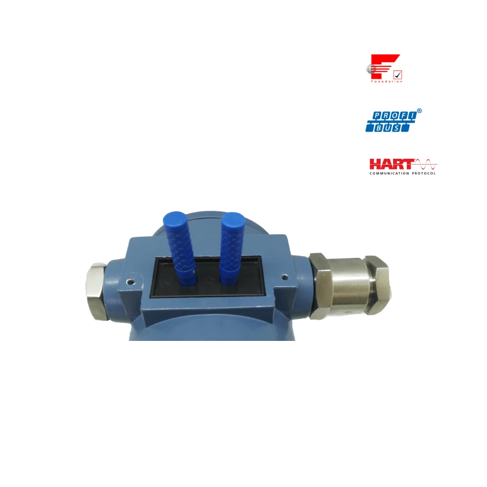
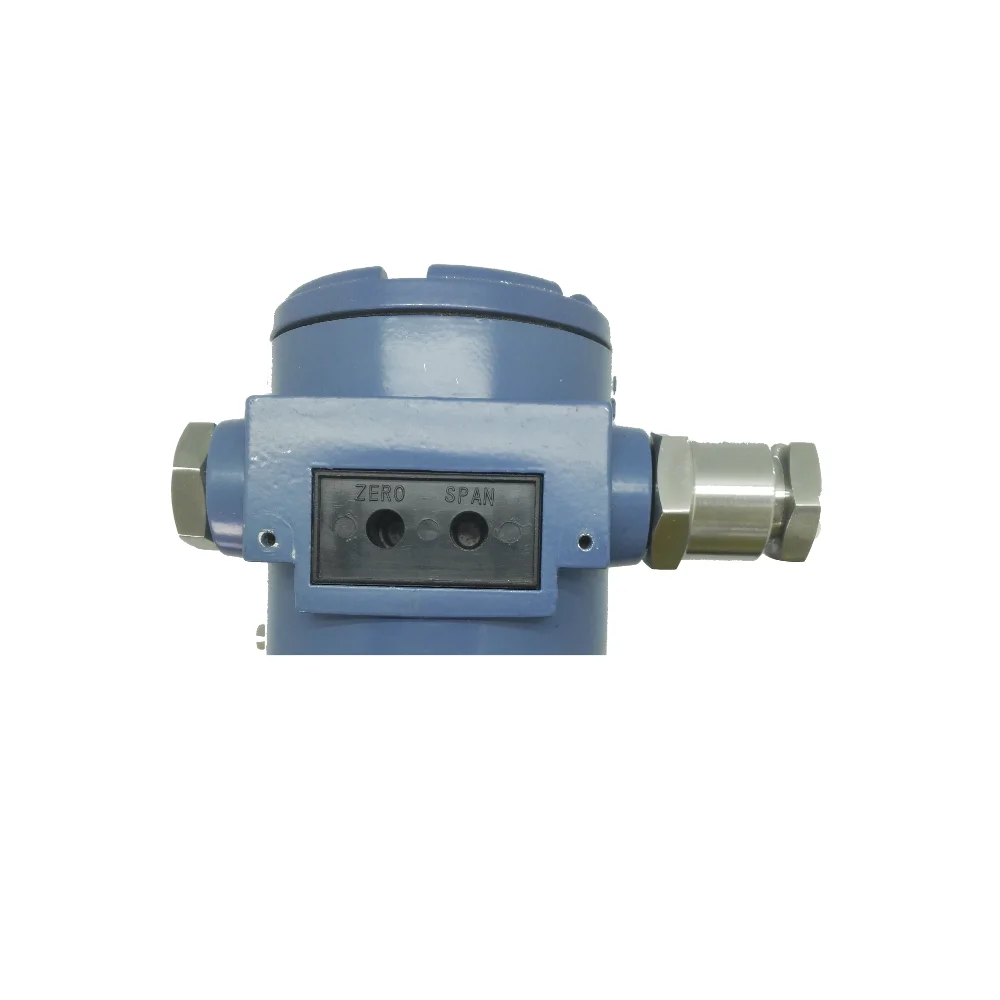
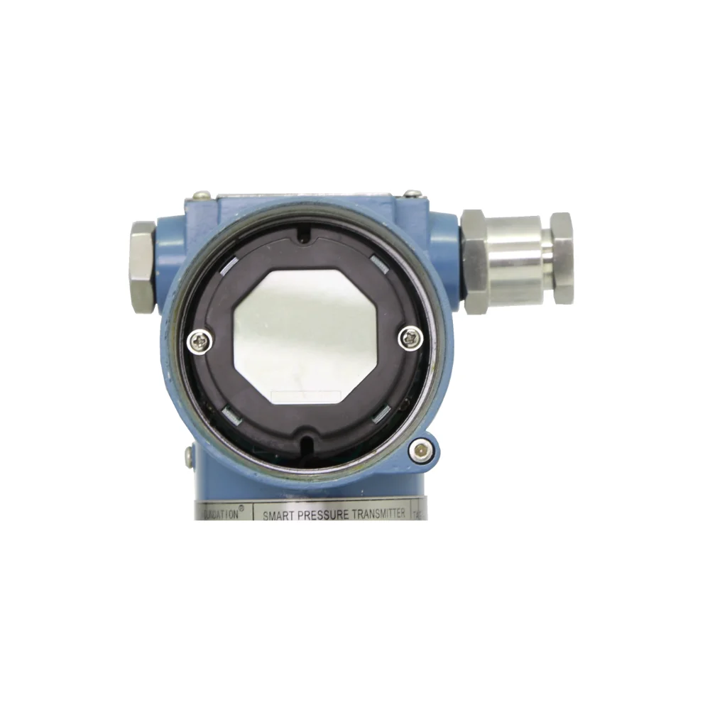
NCS-PT105 Series of Intelligent Pressure Transmitters, complied with HART Protocol, have been used to measure pressure, level, flow and other industrial parameters, which have been widely used in petroleum, chemical, metallurgy, electricity, cement, etc. NCS-PT105II series Smart Pressure Transmitter with advanced, mature, reliable 3151 capacitance sensors has been designed meticulously by combining advanced microprocessor technology and digital capacitance measurement technology. The powerful functions and high-speed computing capability of the microprocessor make it have excellent qualifications such as smart, high precision, high reliability, stable zero and so on. Its LCD can display many physical parameters (e.g. pressure, temperature, current and so on). It can realize the functions such as zero adjustment, range settings by key-press operation, and it is easy for field testing. NCS-PT105II series Smart Pressure Transmitter supports HART, FF, and PA protocol and can measure pressure, differential pressure, liquid level, flow, and other industrial parameters. It can be widely used in the petroleum, chemicals, electricity, and metallurgical industries, etc.. |
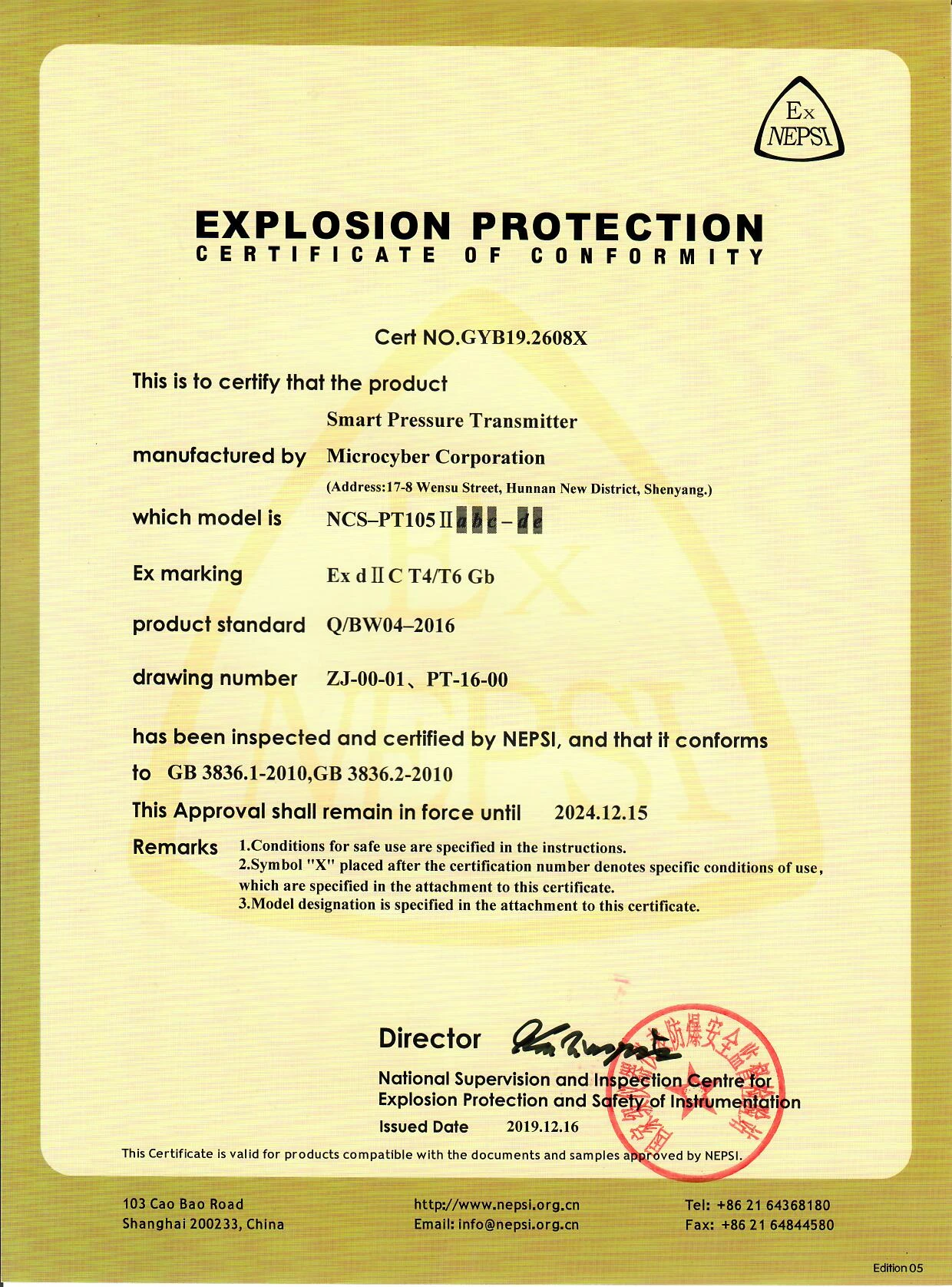
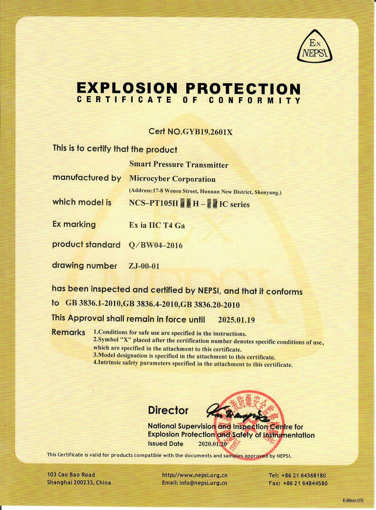
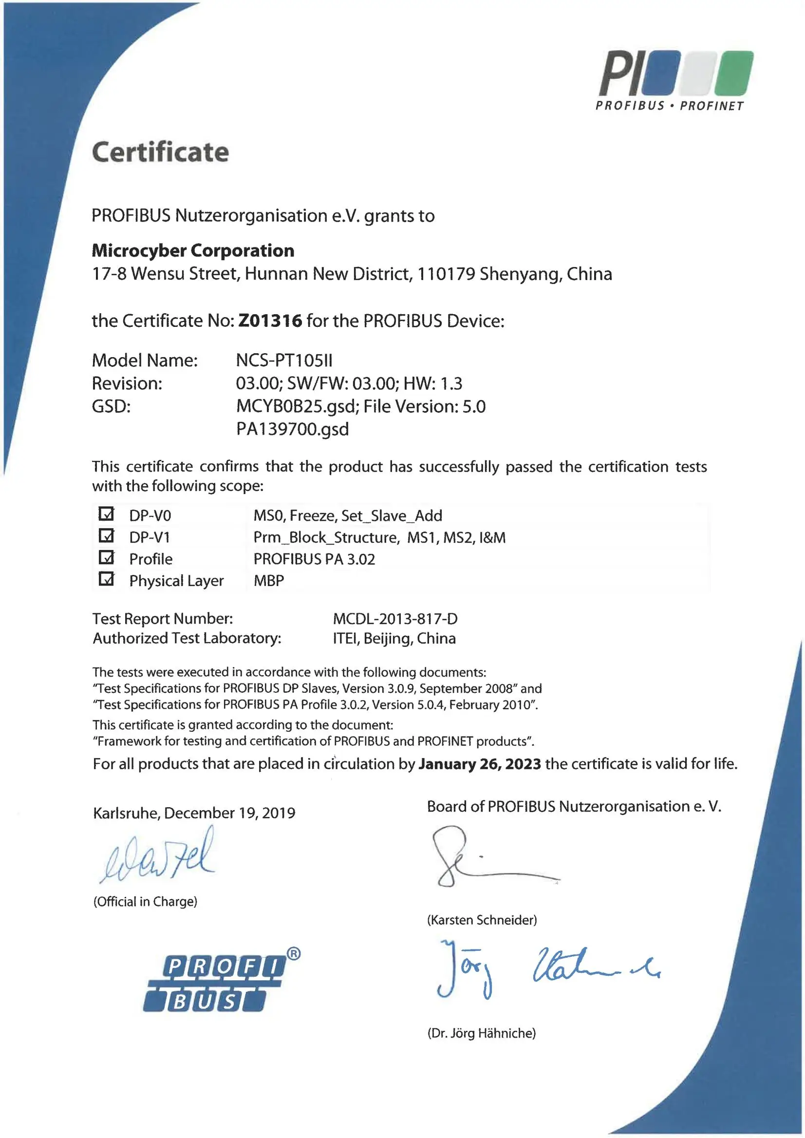
CERTIFICATE
Pressure Transmitter Certificate
![]()
INSTALLATION
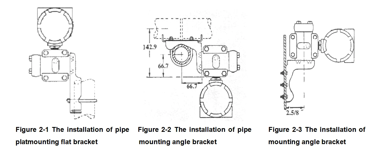
Installation
The measurement accuracy of the smart transmitter depends largely on the correct installation of the smart pressure transmitter and the pressure inlet tube. In particular, the measurement of the flow mainly relates to the correct installation of a measurement device. Transmitter Installation For transmitter installation, three types of brackets are provided (pipe mounting flat bracket, pipe mounting angle bracket, and plate mounting angle bracket). Accordingly, there are three installation methods as the following. The installation of pipe mounting flat bracket: the typical installation as Figure 2-1 shows. Fix the transmitter in a flat bracket using the four bolts provided, and then fix the flat bracket on the vertical pipe of Φ50mm around with the U-shape bolt provided. The installation of pipe mounting angle bracket: the typical installation as Figure 2-2 shows. Fix the transmitter in the angle bracket using the four bolts provided, and then fix the angle bracket on the horizontal pipe of Φ50mm around with the U-shape bolt provided. The installation of plat mounting angle bracket: the typical installation as Figure 2-3 shows. Fix the transmitter in the angle bracket using the four bolts provided, and then fix the angle bracket on the plate with the M10 bolt. |
![]()
Inlet Pressure Pipe Installation
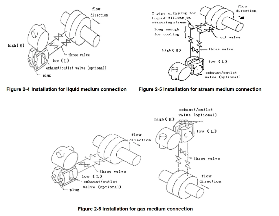
The correct installation of pipeline depends on the measurment medium. Smart transmitter can measure liquid, steam or other gases. The pressure port, smart transmitter and related position of flow pipe are different according to different measurment medium. Liquid: The pressure port must be selected on side of the flow pipe to avoid slag deposition. Smart transmitter should be installed under the pressure port, so that the gas can be drained into flow pipe. As shown in Figure 2-4. Stream: The Inlet pressure pipe must be installed on the side of the flow pipe, and smart transmitter must be installed under the pressure port. The inlet pressure pipe should be filled with water to prevent the direct contaction between smart transmitter and stream. Smart transmitter should not exceed the working temperature limit when stream or other high-temperature medium is measured. As shown in Figure 2-5. Gas: The pressure port should be installed on the top or on the side of the flow pipe. Smart transmitter should be installed on the top of the pressure port, so that the liquid can be drained into flow pipe. As shown in Figure 2-6. |
![]()
Notes:
1) The inlet pressure pipe should be as short as possible in the case of meeting the needs. 2) Corrosive or overheated medium should not be contacted with the transmitter directly. 3) The inlet pressure pipe should be installed in the place where the temperature gradient is low and fluctuation is small. 4) Working temperature limit must be paid attention to when high temperature medium is to measure. 5) For differential pressure transmitter, the two inlet pressure pipes should be kept at the same temperature, and the hydraulic height should be kept balance (For differential type). 6) The inlet pressure pipe should use large-diameter pipe as far as possible in case of the friction effect. 7) For differential pressure transmitter, the liquid-level of the two inlet pressure pipes should be kept at the same height when isolating gas is used. 8) When injection system is used, the system should be as close as possible to the pressure port of flow pipe. And the purifying liquid should get through from the pipes of the same size, length of pipes to the transmitter. Also the injection liquid through transmitter should be avoided (For differential type). |
WORKING PRINCIPLE
Introduction for Working Principle
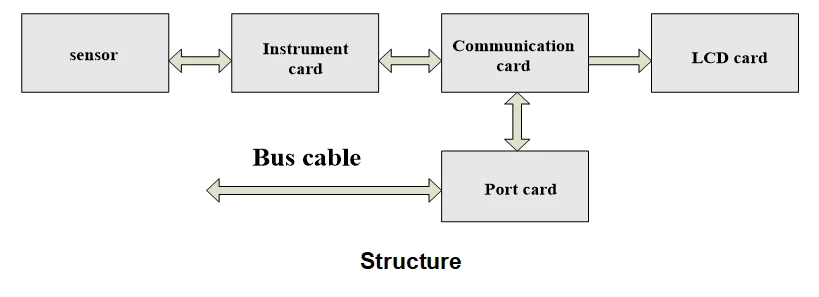
The measurement principle of smart transmitter based on the 3151 capacitive pressure sensor, using advanced micro-controller technology, sensor digital measurement technology and high accuracy algorithm to ensure the high-precision pressure measurement. The advanced HART, FF H1 and PROFIBUS PA Fieldbus technologies are used respectively by the communication interface of smart transmitter. The logical structure of smart transmitter, which is the same, can be divided into five parts: sensor, instrument card, communication card, LCD card and port card, as picture shows. The FF, PA Smart Transmitters are identical in terms of hardware due to the same physical layer specification, the communication card and port card of the FF, PA Smart Transmitters are different from those of Hart, but other parts are the same. |
![]()
Introduction to Working Principle
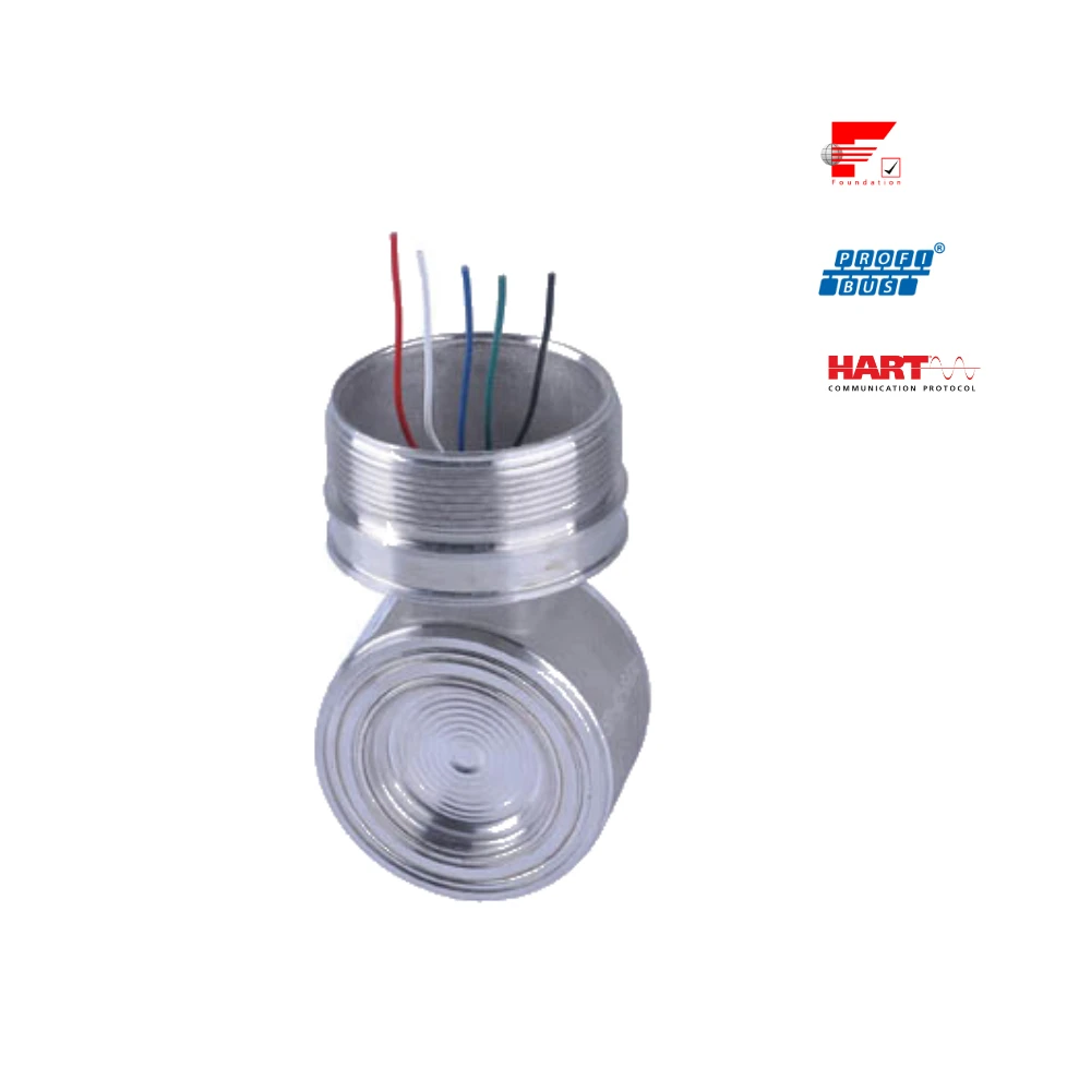
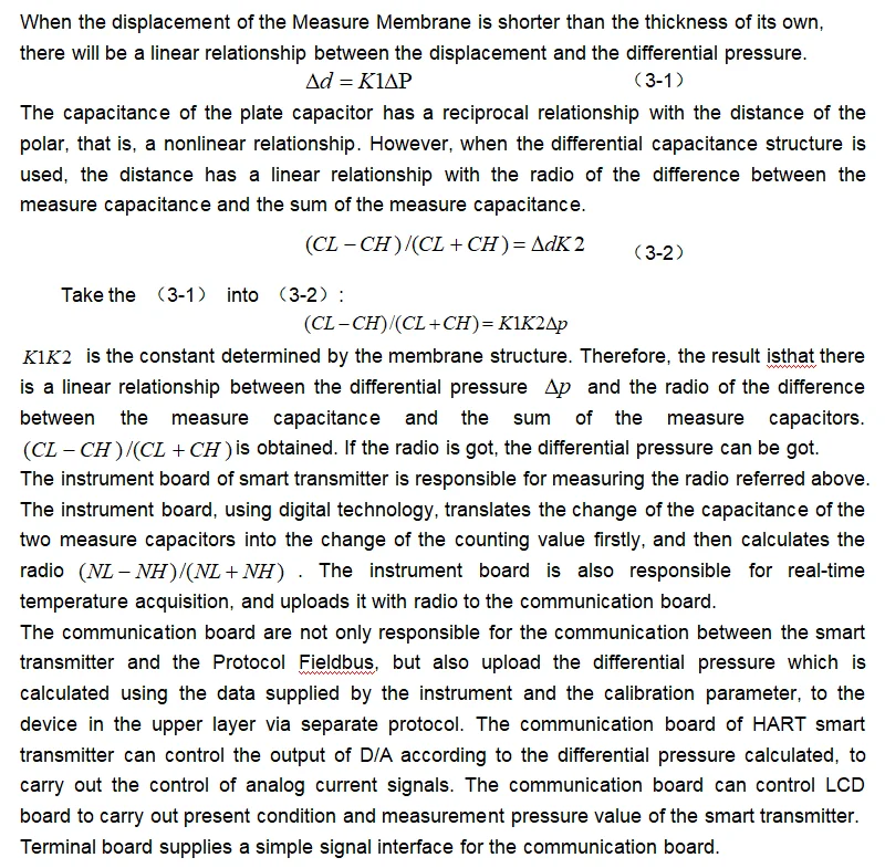
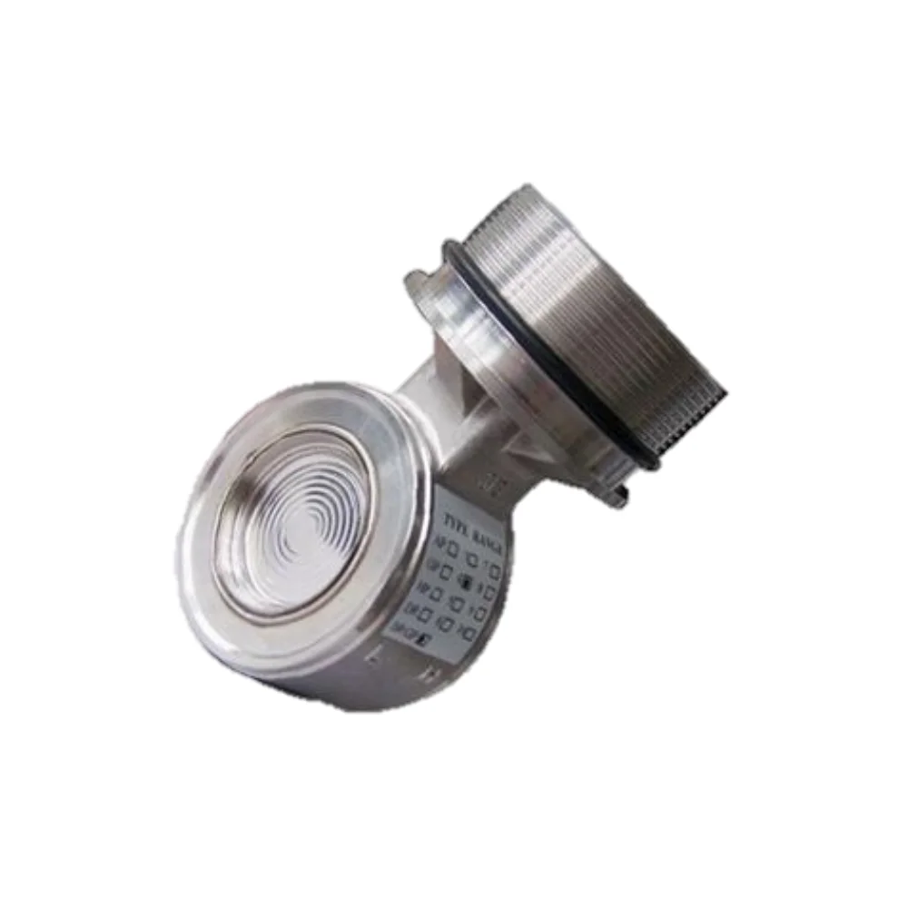
The widely used 3151 capacitive pressure sensors, which were developed by Rosemount initially in USA, have been produced on a large scale in China. The core of its sensor is differential capacitive membrane, as picture shows. There are two measurement capacitances CH and CL distributed in differential capacitive membrane. The two measurement capacitances are almost equal to two plate capacitances because of their mechanical structure. The two measurement capacitances share one polar plate, which is a measure membrane in the center. And the other polar plate is fixed on the two sides. When the pressures of two sides are equal, the measure membrane is in the center, the capacitances of two sides are equal too. But when the pressure of high pressure side is higher than that of low pressure side, the guide pressure liquid filled in the membrane guides the differential pressure, so that the measure membrane moves to low pressure side. As a result, the capacitance of high pressure side is lower than that of the low pressure side. |
![]()
![]()
CONSTRUCTION
Construction Introduction
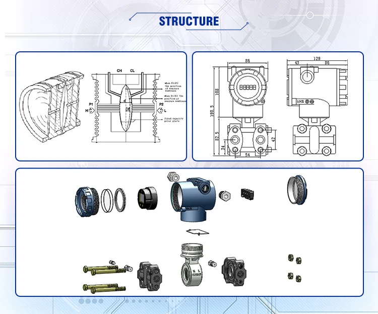
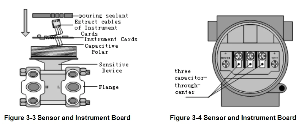
The differential capacitance membrane is encapsulated in the sensor, and through three capacitance polar cables which are extracted. The capacitance polar are welded on the measurement membrane and fixed polar separately. And the Flange is tightly-ferruled on the both sides of the sensitive device by four bolts. As a result, the sensor is formed, as Figure 3-3 shows. |
![]()
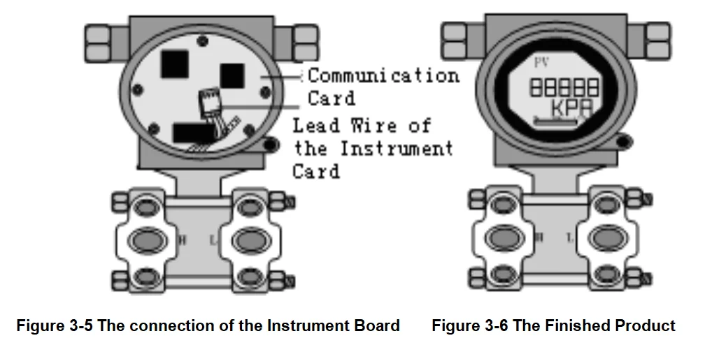
The instrument board is installed in the sensor device of the smart transmitter. The capacitance polar of the sensing device is welded on the interface of the measurement capacitance in the instrument board. The pouring sealant, which has effects of insulation and conduction, fixes the instrument board in the cavity reserved by the sensitive device. And the four-core cable of the instrument board is reserved outside, which can be used to connect the communication board. Three capacitance-through-center with thread are wrung in the hole of the housing, one polar is extended to the cavity of the instrument and connected to the terminal board, and the other one is welded on the three terminals on the terminal block separately. The bus signal is supplied to the terminal board through capacitance-through-center, as Figure 3-4 shows. The terminal board is fixed on the bottom layer of the housing in the cavity of the instrument and welded capacitance-through-center. The communication board is inserted in the terminal board, and fixed by the bolts. The Four-core cable of the instrument board is extended into the cavity of the instrument and inserted in the communication board, as Figure 3-5 shows. |
![]()
![]()
![]()
Exhibition
Microcyber has participated in many significant international exhibitions, such as ISA, Automation World, CIIF, Hannover Method, Automation Expo and MICONEX.
Microcyber will keep moving on and hope to meet you in the near future. |
![]()
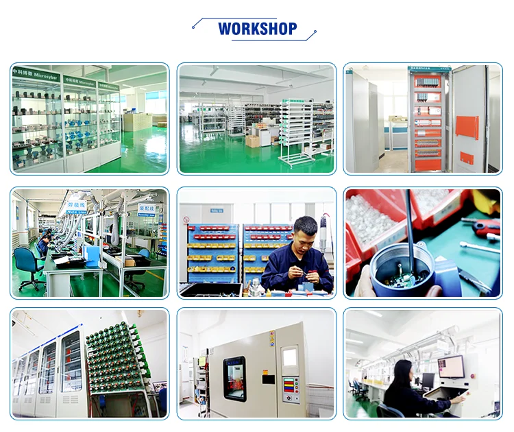
Workshop
Microcyber's production center is 1700m2, with the anti-static ground, ventilating system, air source transporting system, temperature, and humidity control system, and production devices.
The production center consists of 4 workshops and 1 professional lab, they are a production workshop, assembly workshop, aging workshop, maintenance workshop, and product lab.
There are professional production lines, pressure transmitter assembly lines, instrument assembly lines, control system module assembly lines, and product testing lines.
Microcyber has a batch capacity for 10 thousand devices per year. |
![]()
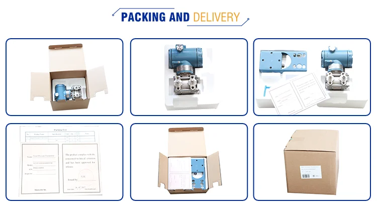
Package
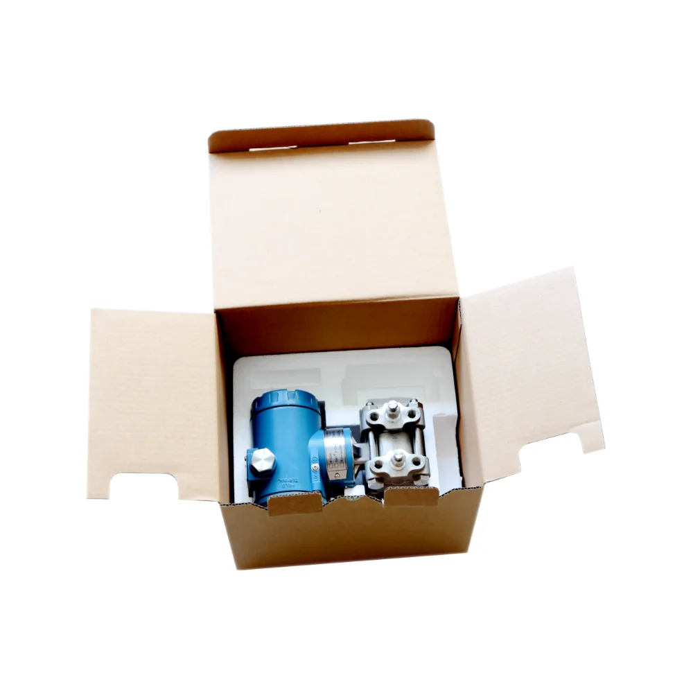
Microcyber Corporation export packaging carton standard: GB/T 5033-1985 "corrugated carton for export products packaging", corrugated carton processing USES corrugated board stipulated in GB5034-85 "corrugated board for export products packaging".
In order to protect the products, Microcyber use paper boxes to package the products.
In order to prevent damage to the goods during transportation, Microcyber will use foam in the cartons to better protect the products.
If the products are too heavy, Microcyber will reinforce them with pallets.
|
FAQ
Q1: Which one is the most popular model?
A1: NCS-PT105IISG and NCS-PT105IISD. Q2: How to install the NCS-PT105II Pressure Transmitter (Capacitance Sensor)? A2:There are three ways to install NCS-PT105II Pressure Transmitter (Capacitance Sensor): installation of pipe mounting flat bracket, installation of pipe mounting angle bracket, and installation of plat mounting angle bracket. Q3: Can I get a free electronic manual? A3:Yes, if you want it, please contact us. Q4: Can you provide OEM service? A4: Yes, we can, such as communication board, we can also provide Fieldbus development toolkit. |