Разделительная машина для орехового ядра, линия обработки орехового ореха
1 400,00 $ - 1 600,00 $


Сохранить в закладки 1600976569433:
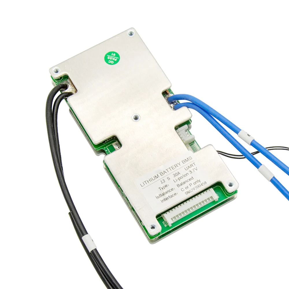
JBD-SP15S020 is an intelligent protection board scheme specially designed for battery packs of electric bicycles and electric motorcycles by Dongguan City Jia Bai Da Electronic Technology Co., Ltd. It can be applied to lithium batteries with different chemical properties, such as lithium ion, Li-polymer. Lithium iron phosphate, etc. The protection board has strong loading capacity and the maximum continuous discharge current can reach 60A.
• 11-15cell series protection
• Various protection functions for charging and discharging
• Discharge overcurrent, short circuit protection functional processes of hardware
• Overvoltage, undervoltage, temperature, overload protection functional processes of software
• Precise SOC calculation with SOC function of automatic learning
• Discharge overcurrent, short circuit protection functional processes of hardware
• Equipped with Bluetooth module with isolatedUART\\RS485 communication
Items | Min. | Type | Max. | Unit | Description | ||
Working humidity | -20 | +70 | ℃ | Normal working temperature range | |||
Storage temperature | -40 | +85 | ℃ | Humidity<90%, No condensation | |||
Protection board size | MAX:140*62*16 | mm | L*W*H | ||||
The above parameters are recommended values. After customers get the protection board, they can change it according to their needs.
Software interface (customer can read the battery data from Computer communication directly, they can observe the charge & discharge state and they can change the protection parameters of battery pack.
Functions | Test items | specification | Unit | |||||
Min. | Type | Max. | ||||||
Operating current | Rated charging current(CC-CV) | 60 | A | |||||
Rated discharge current | 60 | A | ||||||
Charger voltage(CC-CV) lifepo4 | Battery series *3.6 | V | ||||||
Charger voltage(CC-CV) Li-ion | Battery series *4.2 | V | ||||||
Over-charge protection voltage lifepo4 | 3.700 | 3.750 | 3.800 | V | ||||
Over-charge protection voltage li-ion | 4.200 | 4.250 | 4.300 | V | ||||
Over-charge protection delay time | 1000 | 2000 | 3000 | mS | ||||
Over-charge protection recovery voltage lifepo4 | 3.550 | 3.600 | 3.650 | V | ||||
Over-charge protection recovery voltage li-ion | 4.100 | 4.150 | 4.200 | V | ||||
Discharge protection | Over-discharge protection voltage lifepo4 | 2.400 | 2.500 | 2.600 | V | |||
Over-discharge protection voltage li-ion | 2.600 | 2.700 | 2.800 | V | ||||
Over-discharge protection voltage | 1000 | 2000 | 3000 | mS | ||||
Over-discharge protection recovery voltage lifepo4 | 2.700 | 2.800 | 2.900 | V | ||||
Over-discharge protection recovery voltage li-ion | 2.900 | 3.000 | 3.100 | V | ||||
Overcurrent protection | Charging overcurrent protection value | 65 | 70 | 75 | A | |||
Charging overcurrent delay | 3 | 5 | 7 | S | ||||
Charging release adjustment | 32 | S | ||||||
Discharge overcurrent 1 protection current value | 65 | 70 | 75 | A | ||||
Discharge overcurrent 1 protection delay | 3 | 5 | 7 | S | ||||
Discharge overcurrent 2 protection current value | 160 | 180 | 200 | A | ||||
Discharge overcurrent 2 protection delay | 100 | 500 | mS | |||||
Discharge overcurrent protection recovery condition | 32 | S | ||||||
Short circuit protection | Short circuit protection delay time | 200 | 500 | uS | ||||
Short circuit protection | Disconnect the load | |||||||
Balanced function | Balanced turn-on voltage li-ion | 3.950 | 4.000 | 4.050 | V | |||
Balanced turn-on voltage lifepo4 | 3.350 | 3.400 | 3.450 | V | ||||
Voltage difference achieves the starting condition | 30 | mV | ||||||
balanced pattern | charge balance | |||||||
Balanced current | 40 | 60 | mA | |||||
High temperature protection for charging | 63 | 65 | 67 | ℃ | ||||
Release value of charging high temperature protection | 53 | 55 | 57 | ℃ | ||||
Low temperature protection for charging | -7 | -5 | -3 | ℃ | ||||
Low temperature protection release value of charge | -2 | 0 | 2 | ℃ | ||||
Discharge high temperature protection value | 73 | 75 | 77 | ℃ | ||||
Discharge high temperature protection release value | 63 | 65 | 67 | ℃ | ||||
Discharge low temperature protection value | -12 | -10 | -8 | ℃ | ||||
Discharge value at low temperature | -2 | 0 | 2 | ℃ | ||||
Internal resistance | Discharge loop internal resistance | / | 5 | 10 | mR | |||
Operating mode | 20 | mA | ||||||
Sleep mode | 200 | uA | ||||||
Sleep delay | no electricit/no communication line/Delay in unprotected state 10s | |||||||
Complete the connection of the protection board, After normal communication, please modify the nominal capacity to the actual capacity of the battery,.and the circulating capacity is set to 80% of the actual battery capacity.
Please note: please make sure the B-thick wire be weld first, then continue to connect other wires, B- wire welding too thin too long or not welding will burn the board! It must be welded with thick short wires!


Новинки товаров от производителей по оптовым ценам