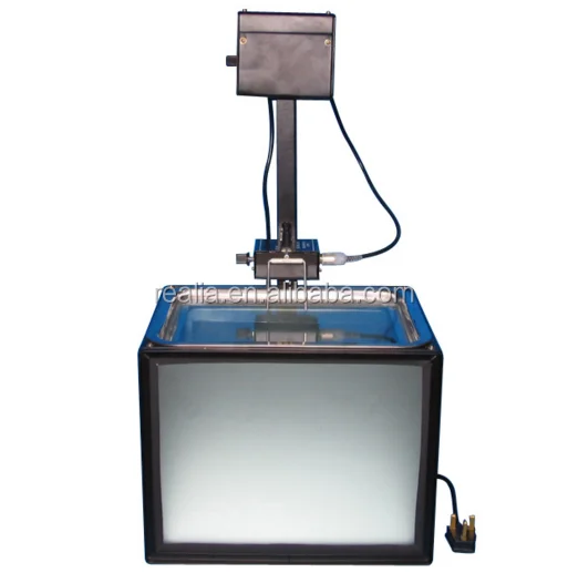
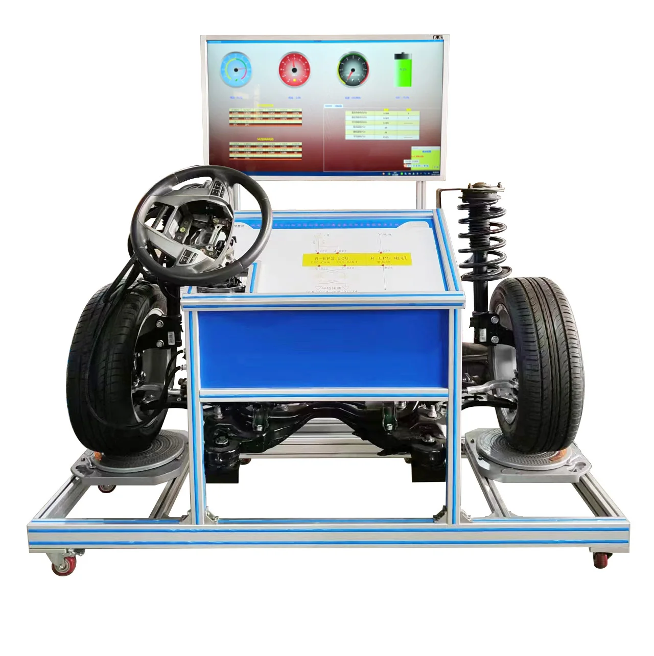
Высокое напряжение и высокий ток реле тренировочная платформа
- Категория: >>>
- Поставщик: Guangzhou Sanxiang Teaching Instrument Co. LtdGuangzhou Ltd
Сохранить в закладки 1601150291081:
Описание и отзывы
Характеристики
Product Description
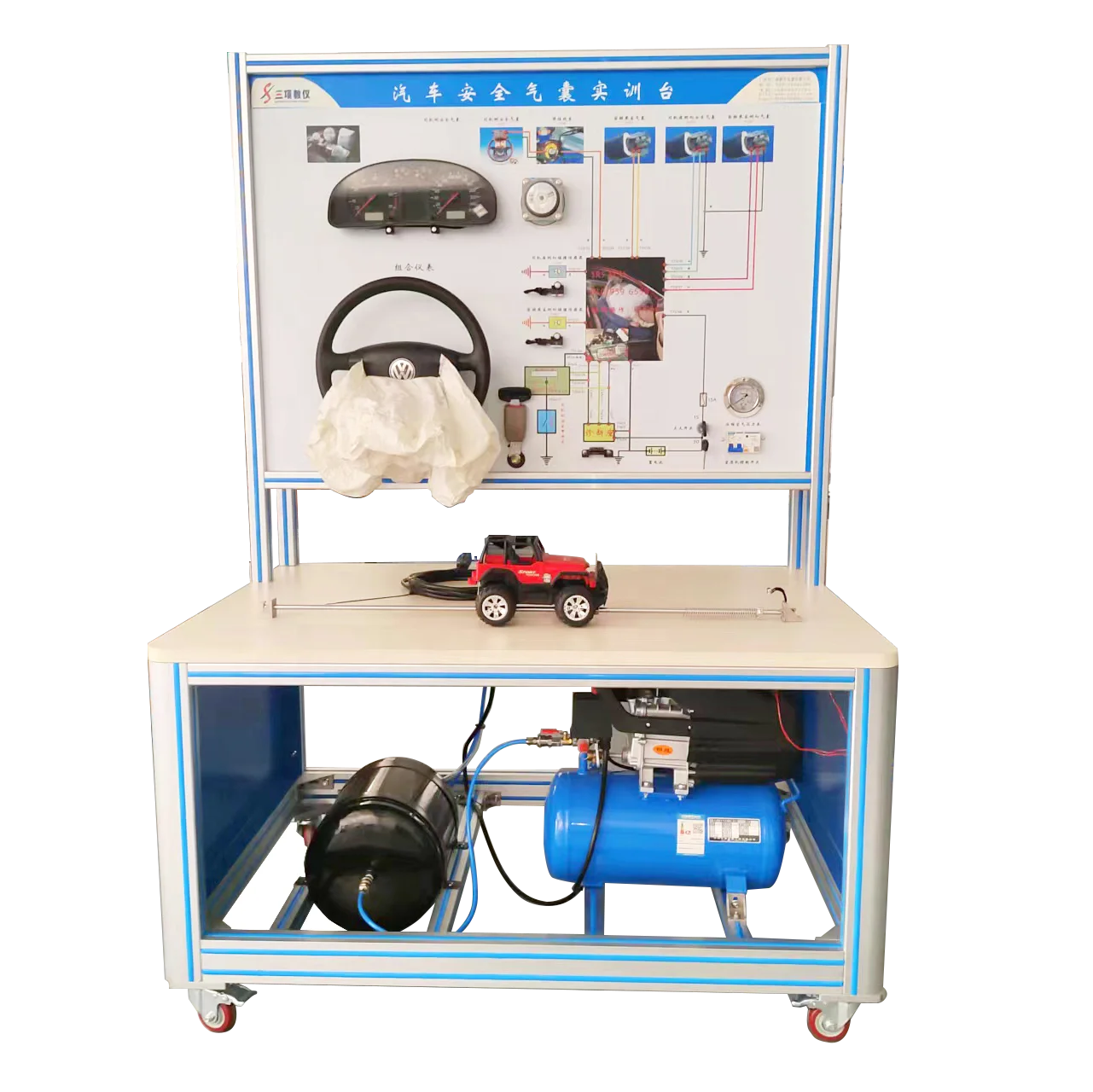
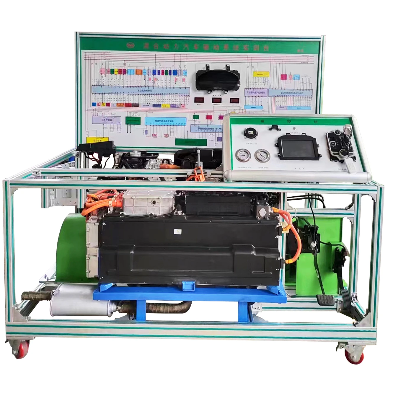
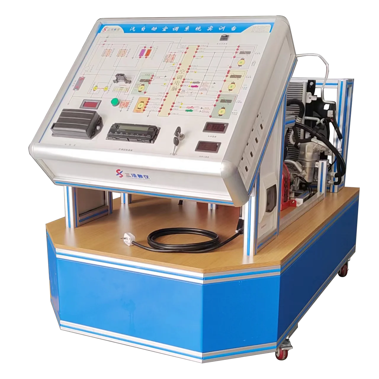
High voltage and high current relay training platform

-Product Overview--
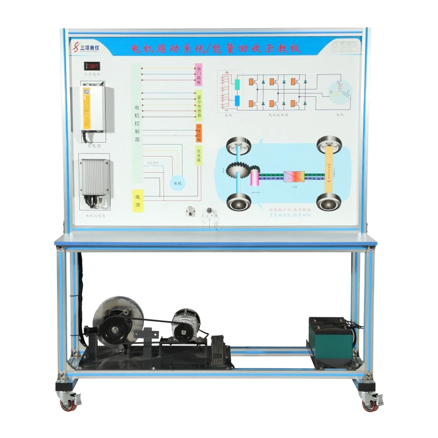
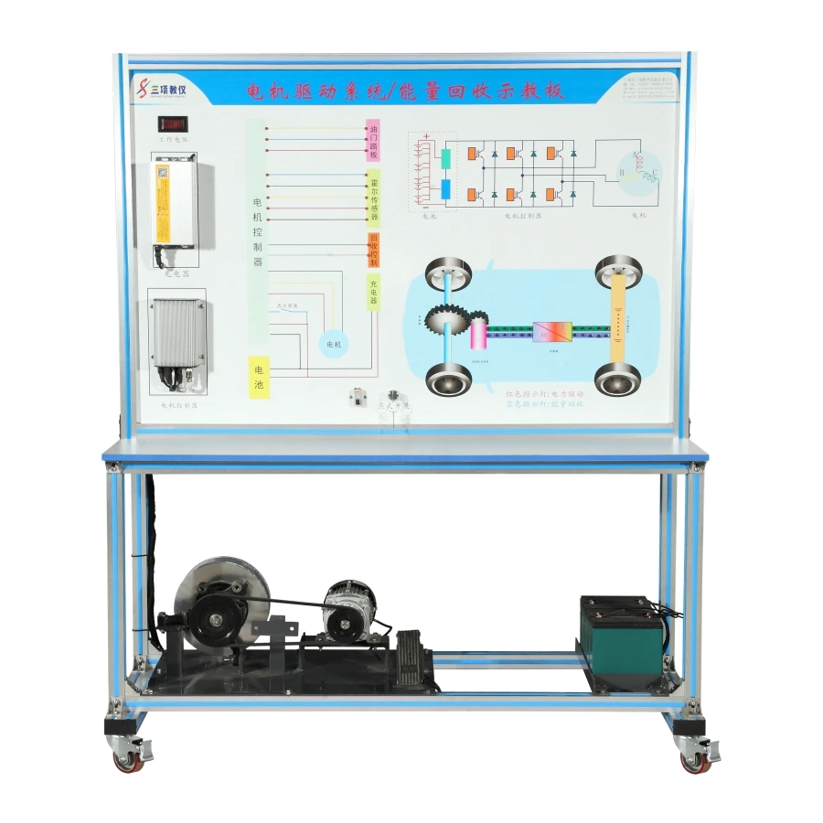
This teaching board is made of electric vehicle related components and control units. It can display the composition and working principle of the motor drive system/energy recovery system, and dynamically demonstrate the working process of the motor drive system/energy recovery system to deepen students' understanding of the structure and working principle of the motor drive system/energy recovery system. Applicable to the practical teaching needs of various types of colleges and training institutions for theoretical learning and maintenance training of motor drive systems/energy recovery systems.
--Production process --
1. Nylon universal casters: With a locking universal caster movement device, it can move freely, making it easy to rescue students;
2. The stand is made of aluminum material, which is moisture-proof, rust proof, beautiful, generous, and durable,
3. The panel is made of high-quality imported aluminum-plastic panels with a thickness of 4mm that are not easily deformed, and the surface is painted with colored spray painted circuit diagrams. 4. Detection terminal 8mm stainless steel terminal;
--Main components--
Motor, motor controller, drive shaft, brake disc, accelerator pedal, LED light, LED controller, voltmeter, movable stand, circuit principle and training panel diagram, supporting user manual, etc,
All components of the motor drive/energy recovery system can fully demonstrate the structure, composition, and working principle of the motor drive system/energy recovery system. Conduct the following experiments:
Machine drive system acceleration and deceleration experiment,
Principle Experiment of Quantity Recovery System
Display the charging and discharging voltage of the motor drive/energy recovery system.
The D flow light dynamically displays the charging and discharging status of the system. When the accelerator pedal is pressed, the voltmeter shows a decrease in voltage. The red LED lights cycle in sequence according to the direction of current flow. When the accelerator pedal is released, the voltmeter shows an increase in voltage. The blue LED lights light up in sequence according to the direction of current flow. When the motor is not working, the LED lights do not light up. The teaching board panel has a complete circuit schematic and detection terminals, which can be used to detect signal parameters of various components such as voltage, current, resistance, etc. through instruments and meters
Technical parameters--
Dimensions: Approximately 1500 * 500 * 1800 (length x width x height)
Operating temperature: -5 ℃~+50 '℃ Main functions-
All components of the motor drive/energy recovery system can fully demonstrate the structure, composition, and working principle of the motor drive system/energy recovery system. Conduct the following experiments:
Machine drive system acceleration and deceleration experiment,
Principle Experiment of Quantity Recovery System
Display the charging and discharging voltage of the motor drive/energy recovery system.
The D flow light dynamically displays the charging and discharging status of the system. When the accelerator pedal is pressed, the voltmeter shows a decrease in voltage. The red LED lights cycle in sequence according to the direction of current flow. When the accelerator pedal is released, the voltmeter shows an increase in voltage. The blue LED lights light up in sequence according to the direction of current flow. When the motor is not working, the LED lights do not light up. The teaching board panel has a complete circuit schematic and detection terminals, which can be used to detect signal parameters of various components such as voltage, current, resistance, etc. through instruments and meters
Technical parameters--
Dimensions: Approximately 1500 * 500 * 1800 (length x width x height)
Operating temperature: -5 ℃~+50 '℃
Specification
Name | High voltage and high current relay training platform |
Origin | China |
Brand | Sanxiang |
Size | 1500*500*1800mm |
Parameters | Customized |
Company Profile


Certifications

Packing & Delivery
Packing : 1set/carton 10set/container
Delivery : 3-30 days after customer place an order fastener bags+cartons+pallets according to customer ' s requirement.
PS:Customer comments will be considered or take, protect the goods from damage will be primary condition.
Delivery : 3-30 days after customer place an order fastener bags+cartons+pallets according to customer ' s requirement.
PS:Customer comments will be considered or take, protect the goods from damage will be primary condition.
FAQ
Why choose us?
A:Because we are the best quality in China.we have the most professional manufacturer,we can provide higher quality goods and first class service.
A:Because we are the best quality in China.we have the most professional manufacturer,we can provide higher quality goods and first class service.
Can you accept OEM and ODM?
A:Of course,OEM/ODM are warmly welcomed,Please send your artwork and requirements to us.We have the fully capacity and rich experience to customize any design,shape and size according to our client's artwork for 10 years.
Can I get a lower price if i order large quantities?
A:Yes,cheaper price with large quantities.
Can I request a sample?
A:If you want our existing sample,please inform us your address & phone number,we will quote the sample charge & express charge to you.The sample will be sent out after receiving payment(within 5~7 days).If you want a personalized sample,please provide your artwork to us,the sampling will take about 15 days.
What shipping methods do you use?
A:For small orders,we usually ship by DHL,UPS, FedEX and TNT,you can receive in 5 to 8 days,For big orders,by sea , the shipping price is more cheaper than air(Different country different shipping time).
What about the after-sales?
A:Our product are brands' quality,if there is any problem,our technicians will give you solution in details,insert related
instructions photos and videos which shows how to operate step by step,and we will keep communicate with you until you understand clearly.
A:Of course,OEM/ODM are warmly welcomed,Please send your artwork and requirements to us.We have the fully capacity and rich experience to customize any design,shape and size according to our client's artwork for 10 years.
Can I get a lower price if i order large quantities?
A:Yes,cheaper price with large quantities.
Can I request a sample?
A:If you want our existing sample,please inform us your address & phone number,we will quote the sample charge & express charge to you.The sample will be sent out after receiving payment(within 5~7 days).If you want a personalized sample,please provide your artwork to us,the sampling will take about 15 days.
What shipping methods do you use?
A:For small orders,we usually ship by DHL,UPS, FedEX and TNT,you can receive in 5 to 8 days,For big orders,by sea , the shipping price is more cheaper than air(Different country different shipping time).
What about the after-sales?
A:Our product are brands' quality,if there is any problem,our technicians will give you solution in details,insert related
instructions photos and videos which shows how to operate step by step,and we will keep communicate with you until you understand clearly.
Похожие товары
Тренировочный тренажер с моторизованной антенной
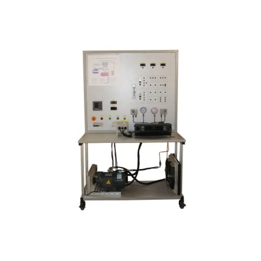
Автоматическая Учебная платформа для кондиционирования воздуха учебное оборудование школы
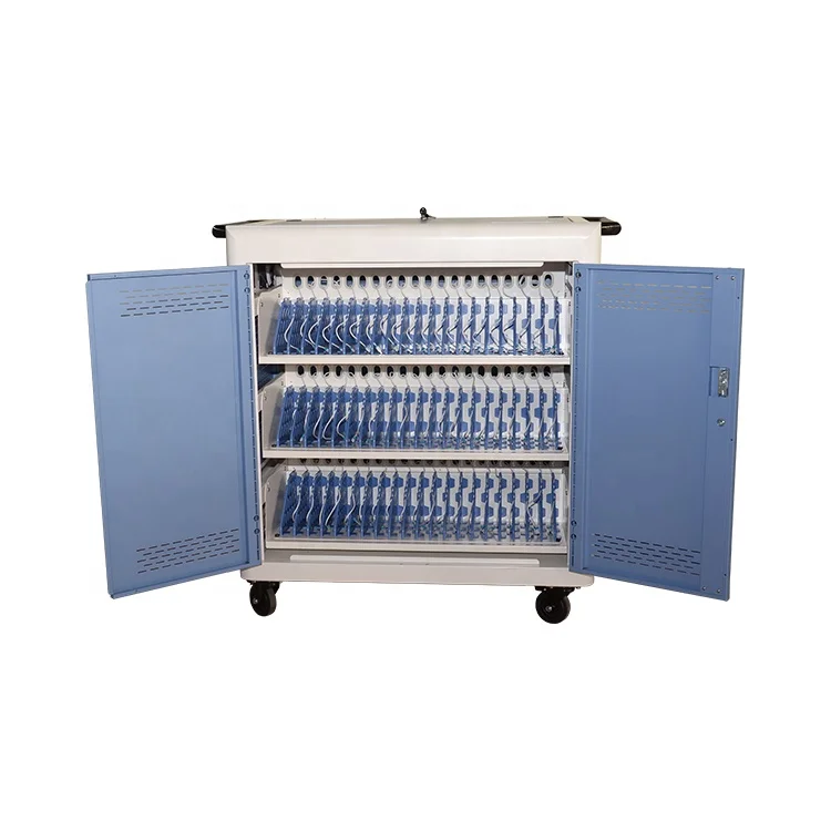
Безопасное обучающее оборудование для хранения планшета ноутбука школьная подержанная зарядная тележка
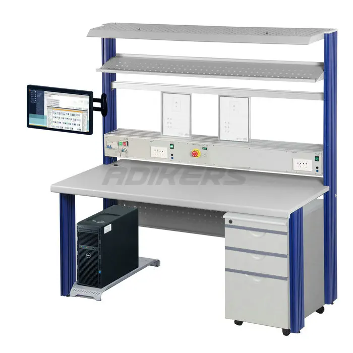
Электронное обучающее оборудование обучающий стенд Тренировочный Набор дидактическое для профессионального обучения технический тренажер Tvet
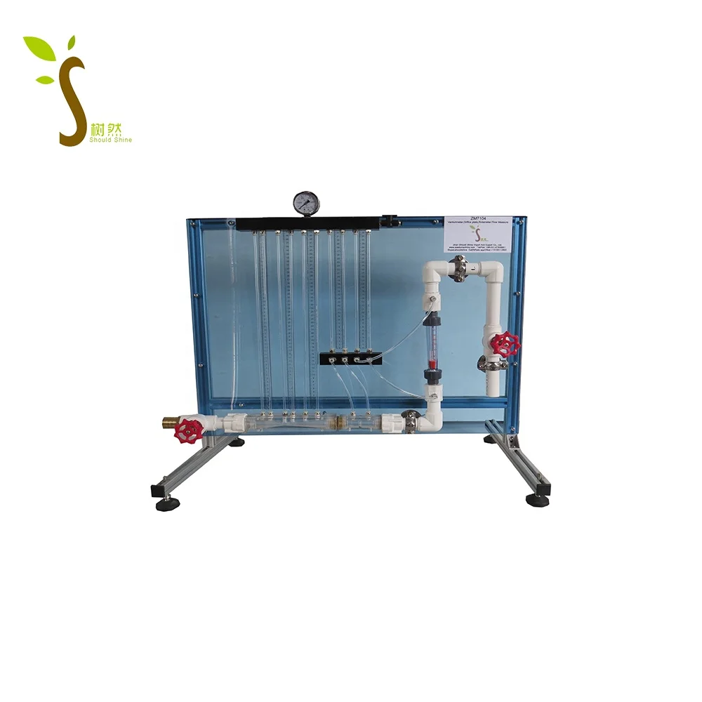
Вентуриметрическая пластина с отверстием ротаметр измеритель расхода учебное лабораторное оборудование для экспериментов по механике жидкости
8 000,00 $
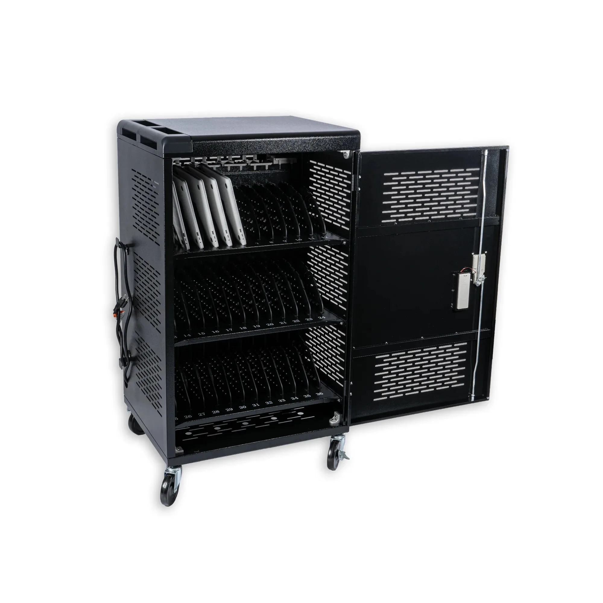
Переносная зарядная станция для ноутбука
279,00-299,00 $
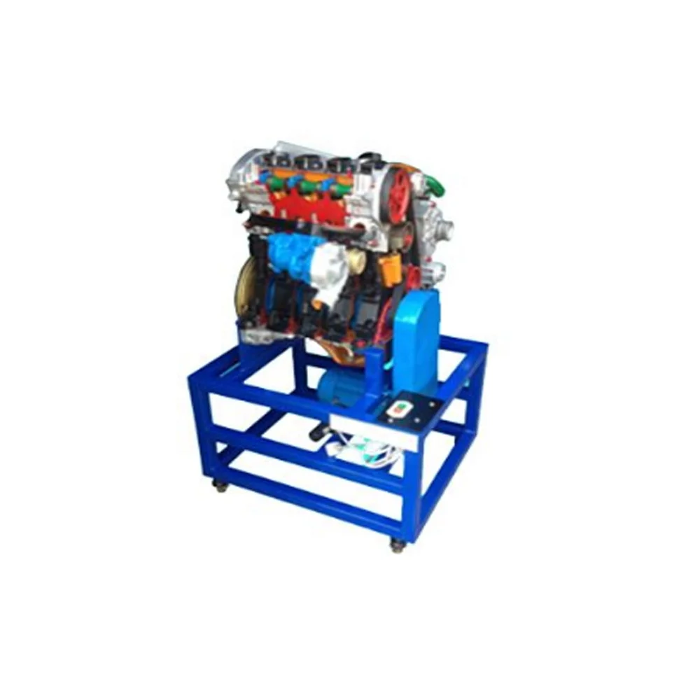
Четырехцилиндровый дизельный тренировочный стенд учебное оборудование автомобильное
Новые поступления
Новинки товаров от производителей по оптовым ценам
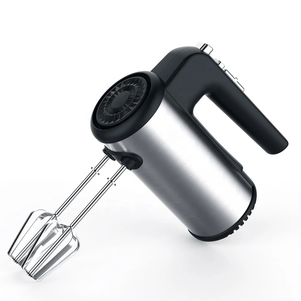
300 Вт безопасный для посудомоечной машины 5-скоростной турбо с крючками для теста, венчик, электрический ручной миксер
571,11-666,30 ₽
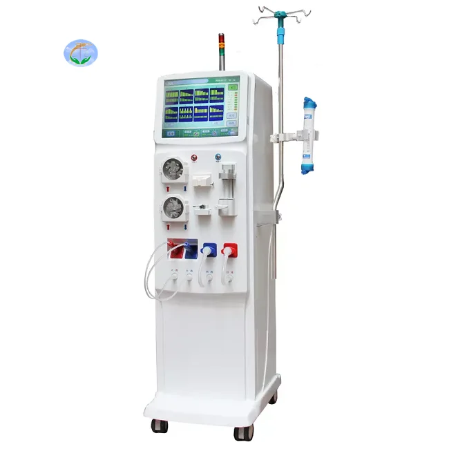
Медицинский портативный прибор для гемодиализа катетер и кровообращения диализа почек ухода за здоровьем
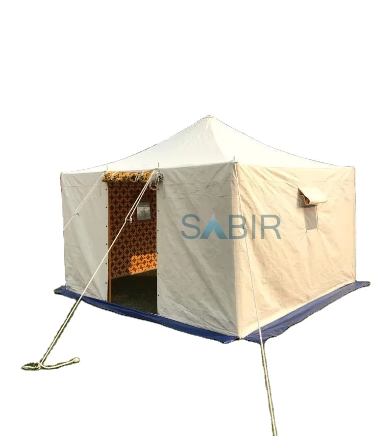
Многофункциональная роскошная водонепроницаемая палатка из брезента для кемпинга однокомнатная всесезонная с настраиваемым размером новый стиль рынка Ближнего Востока
45 688,76-56 159,10 ₽

Санитарно-гигиеническое сиденье для
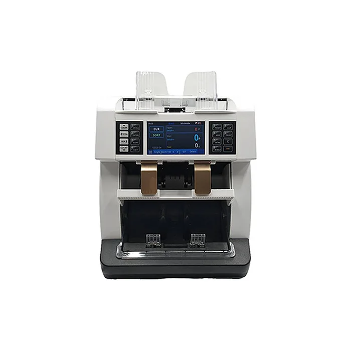
Счетчик купюр с низким уровнем шума на тонкопленочных транзисторах, автоматическое определение разных валют, 4,2 дюйма
50 448-52 351,70 ₽
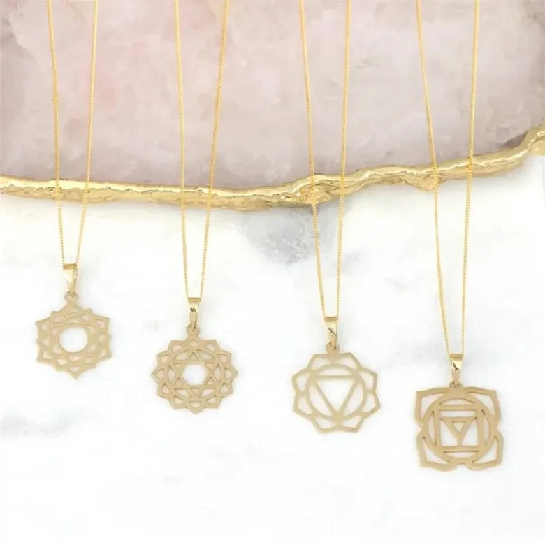
Ожерелье из нержавеющей стали изящное ожерелье с чакрами на заказ модное позолоченное ювелирное изделие водонепроницаемой подвеской без
121,84-217,03 ₽
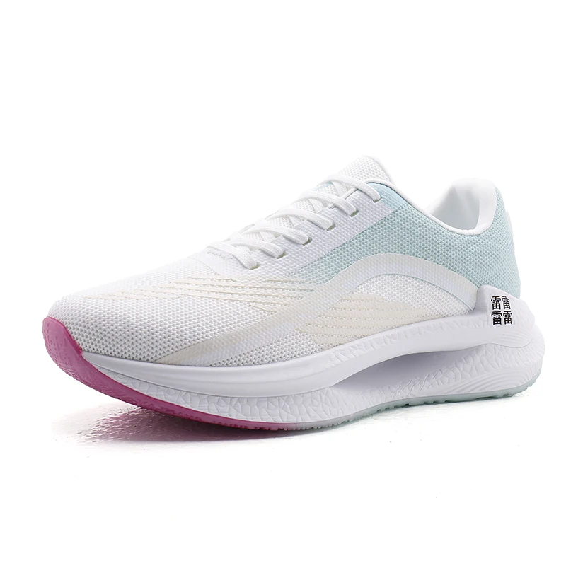
Мужские спортивные кроссовки с логотипом
856,67-999,45 ₽
OEM ODM, настоящее изобретение, персонализированный прямой автоматический открытый пользовательский логотип, рекламный зонт для гольфа с логотипом для отелей
842,39-938,53 ₽