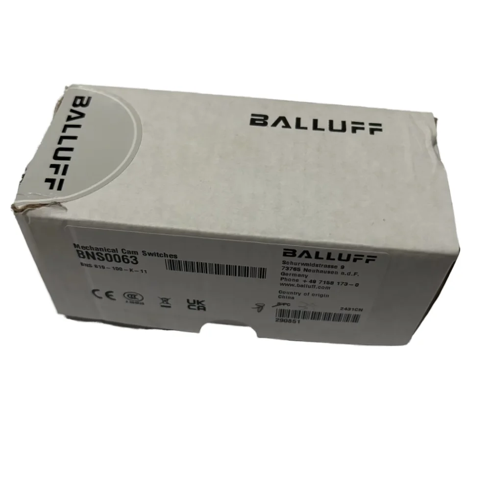
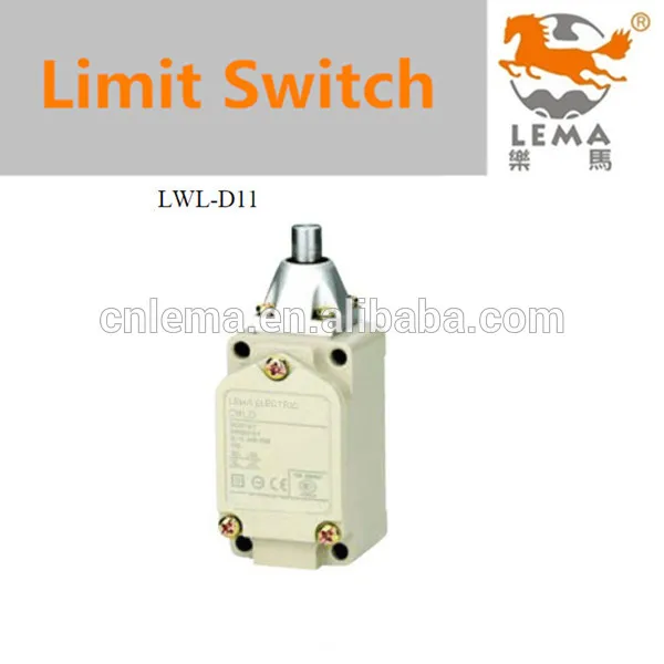
SiRON K090 9 Q3 NC не тип механический электромагнитный предохранительный переключатель

Сохранить в закладки 1601225939909:
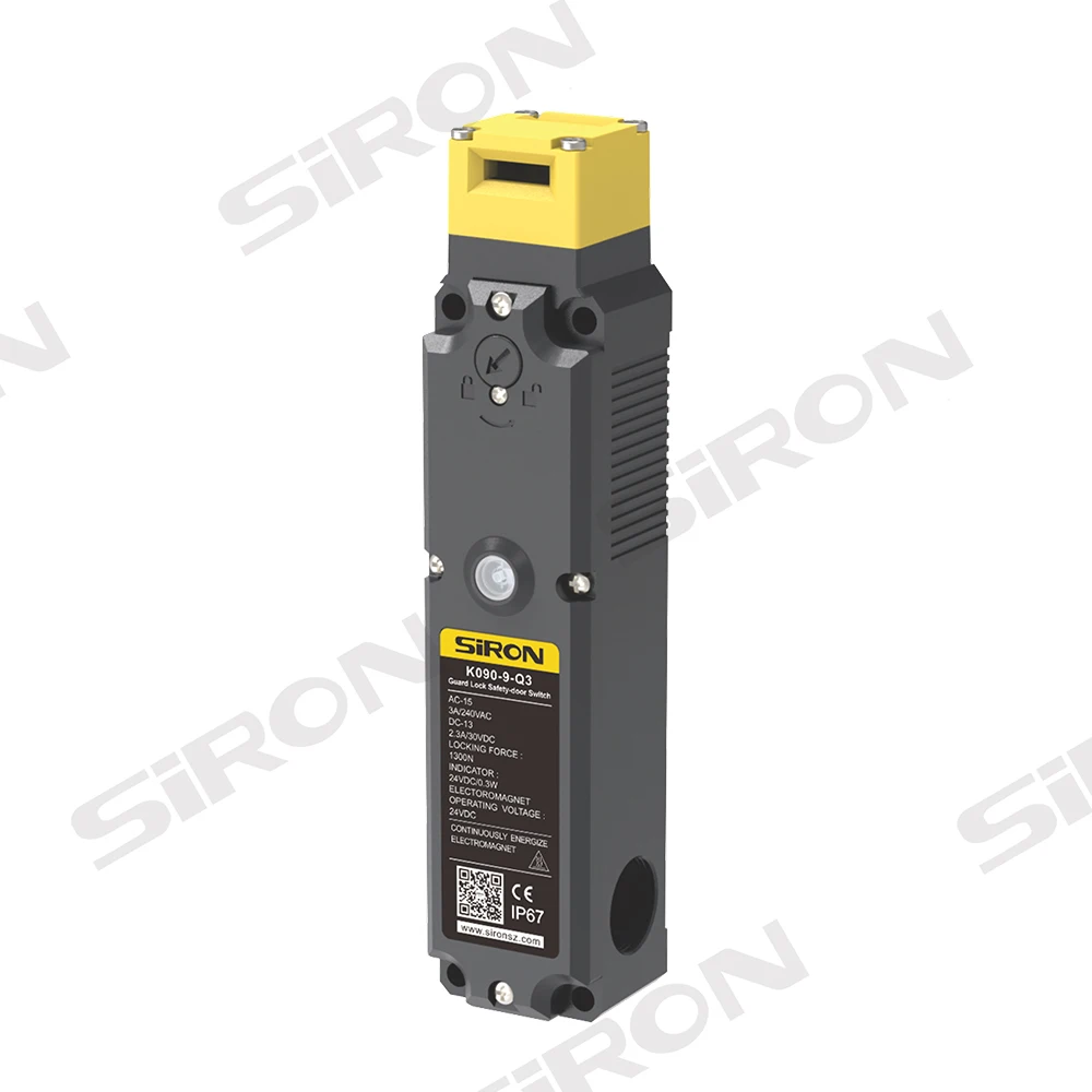
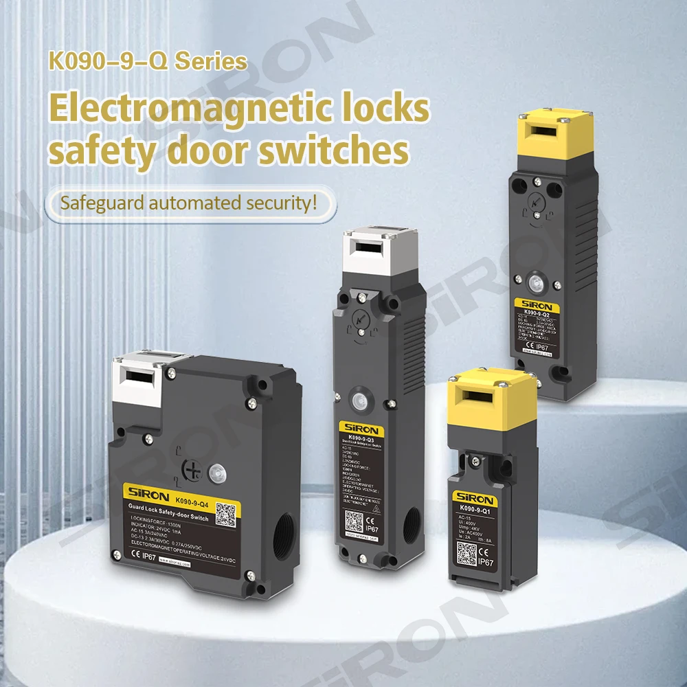
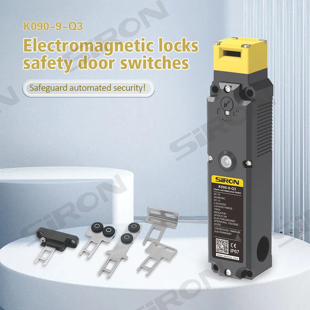
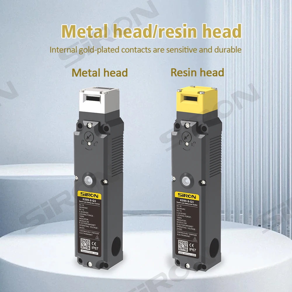

Цена:4 724,17-6 850,05 ₽*

Количество:

  • В избранное

Описание и отзывы

Характеристики


Features


* Suitable for standard load and small load;
* The NC contact is a direct disconnect action contact;
* Up to 3 sets of contact structure, optional 2NC+1NO or 3NC;
* Can adjust 8 ways to insert the operating key to meet different installation positions;
* Operating key and electromagnetic lock safety door switch universal.


About selection


Selection example: K090-9-Q3-A4-R-B indicates K090-9-Q3 series, mechanical locking/electromagnetic release,
built-in switch 2NC+2NC,The head is made of resin and has a back unlocking position.


Specification


K090-9-Q3 series
Solenoid characteristic
400V
Rated operating voltage
DC24V±5%
Rated current
200mA(initial value)
Rated power
4.8W
Insulation
Class B (130℃)
Indicator characteristic

LED luminous color
Green
Rated voltage
DC24V
Rated current
1mA
Peculiarity


Life span
Machine
More than a million times
Electric
More than 150,000 times
Allowable operating speed
0.05~0.5m/s
Allowable operating frequency
Maximum 20 operations/min
Forced breaking force
≥80N
Force disconnect operating distance
≥10mm
Drawing strength atlock
1300N
Ratedinsulation voltage (Ui)
300V
Ratedimpulse withstand voltage (Uimp)
2.5kV
Category of use
AC-15
DC-13
Rated operating voltage (Ue)
240V
30V
Rated operating current (le)
3A
2.3A
Ratedlimited short circuit current
1000A
Rated open thermal current (Ith)
10A
Ambient temperature
-20 ~ 60℃(no freeze)
Ambient humidity
Less than 85%Rh
Head mounting direction
Four mounting directions (front side by default)
Pipe diameter
M20
Shell material
PA66 Antiflaming
Contact material
Silver alloy gilding
Class of protection
IP67(except key operating hole)


Note: 1. The above values are initial values;
2. The contact of the switch is shared by standard and small loads, but the contact that operates on a certain load cannot be connected to a smaller capacity load for use. Otherwise, the contact surface may be damaged and the reliability of the contact may be reduced.


Dimensions


Operating circuit and operating characteristics


Mechanical locking
K090-9-Q3-A8~K090-9-Q3-A14 * Please refer to next pages


Operating circuit and operating characteristics


Mechanical locking
Note: The lock status of the front door before wiring and power on, and when emergency situations such as power on occur, the lock of the operating key can be manually unlocked.


Electromagnetic lock setting
Note: After manually unlocking, the safety door is in the open state, do not apply voltage to the electromagnet for a long time;The safety door is open. Do not use the manual unlock function.


Contact form


The following contact forms insert the operation key and are locked


Component installation guide


Back unlock kit:
1, Casing (length according to the switch fixing plate or door frame thickness customized)
2, Casing limit plate
3, M4 wire (3)
4. Metal knob


1, The electromagnetic lock switch is first installed on the switch fixing plate or door frame;
2. Put the sleeve through the
switch fixing plate or door frame as shown in the picture into the unlock knob on the back of the electromagnetic lock switch;
3. Install the casing stop plate on the switch fixing plate or door frame with M4 wire.
1, The metal knob into the sleeve, and align the axis of the two holes;
2. Tighten with M4 screws.
1. The installation is complete as shown in the figure;
2, the metal knob can only be rotated 90° clockwise.


Instructions for use
1. The back unlock knob is a safety measure for emergency refuge when the operator is accidentally stranded
in the safety ou(dangerous area).
2. Rotate the 90° metal knob clockwise to release the lock and open the door.
3, If you need to restore the locked state, please turn the metal knob 90° counterclockwise.
4, the metal knob in the unlock position, even if the door is closed, the door can not be locked.


* Notice
1, please be sure to install the back unlock knob in the safety fence (dangerous area) can operate.
2, please do not use tools to operate the back unlock knob, or excessive force and to the direction other than the operation
direction, and beyond the rotation Angle range of force, so as to avoid damage to the knob parts and lead to unable to operate.


Installation precautions
1. First, insert the operation key into the head operation hole, then loosen the 4 screws at the top of the head, and finally rotate the head direction to select the appropriate operation keyhole position before installation.


Похожие товары

Новые поступления

Новинки товаров от производителей по оптовым ценам