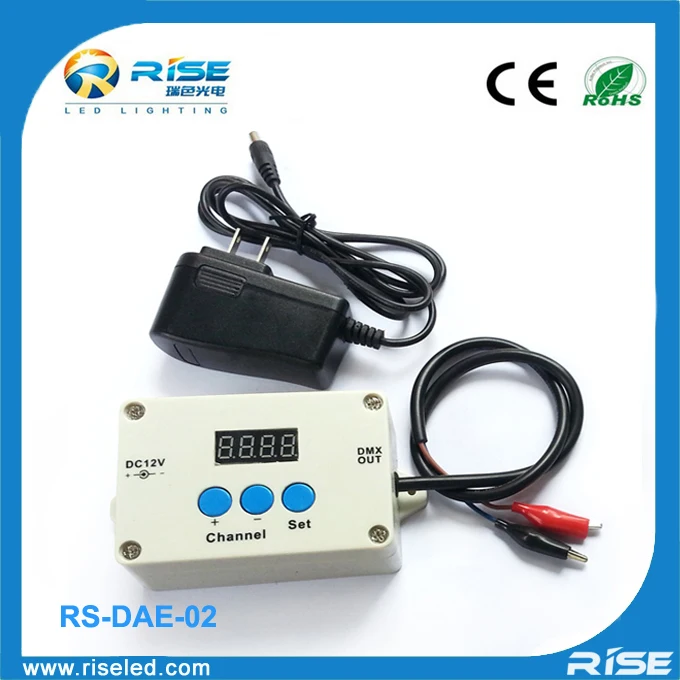
Запись адресов DMX для светодиодной ленты DMX512
- Категория: >>>
- Поставщик: Shenzhen Rita Lighting Technology Limited
Сохранить в закладки 60436855652:
Описание и отзывы
Характеристики
Wiring and fixtures are as follows:
Use a four-core output of the male and female lugs correspondence pick up signals match as follows:
VIN <=> +24 V
ADD <=> ADD (write code input lines)
GND <=> GND
DATR <=> DAT (parallel signal bus)
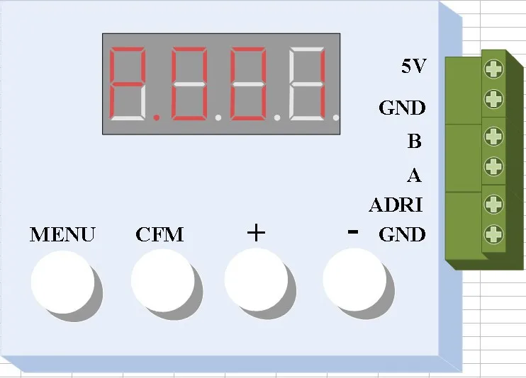
Or use a three-core, a core of two male and female connectors, signal matching as follows:
Three-pin connector docking DAT, ADD, GND;
Two pin connector docking VDD, GND;
Inputs using a three-pin and two two-core wiring connector, the signals are assigned as follows:
Three-core signal output terminal connected to the first signal control system to match the following:
GND <=> GND
A <=> A or D +
B <=> B or D-
When you start writing code is not connected to the controller three core lugs
Two core lug signal signal allocated as follows:
Two-wire connection provides power supply to the VIN and GND
Two core then write code signal line GND ADD and provides write code signal
When writing code two wires connected to the power supply, then the two cores to write code to write code port, where ADD <=> D +, GND <=> GND
The effect of the normal three-pin wiring ran head-to-controller, two-core wiring connected to the power port power head


Похожие товары
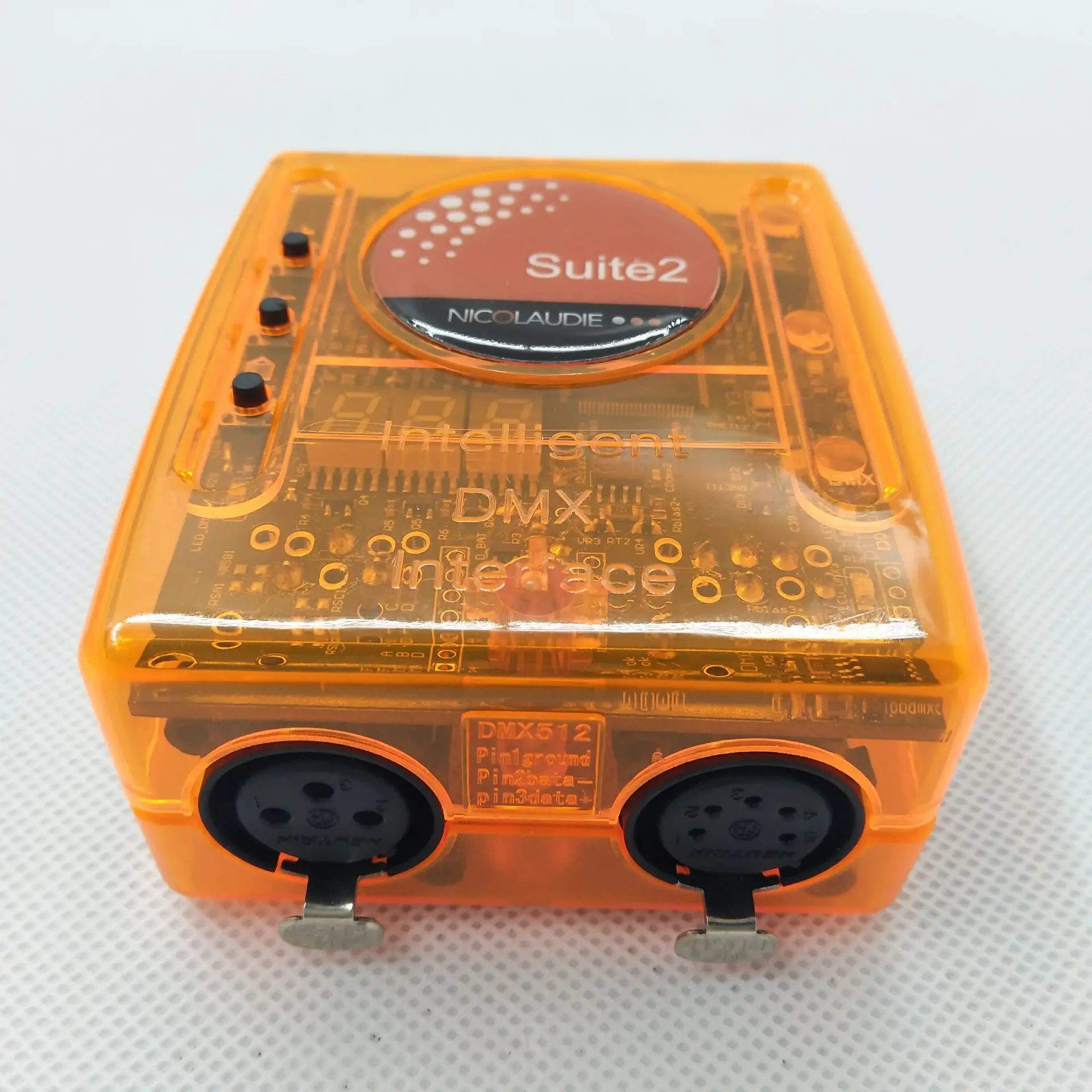
1024 sunlite 2 * DMX512 выходной светодиодный контроллер, сканирование библиотеки, редактор
13 783,57 ₽
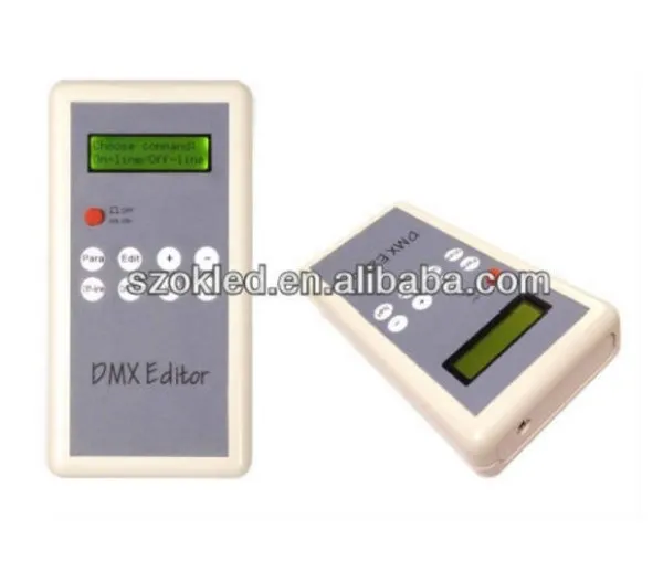
Лидер продаж! Ручной DMX ID редактор/led dmx редактор

Лидер продаж! Ручной DMX ID редактор/led dmx редактор
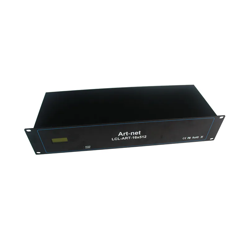
Контроллер DMX 512 light artnet dmx с разъемом neturix XLR
47 039,17 ₽ - 49 227,03 ₽
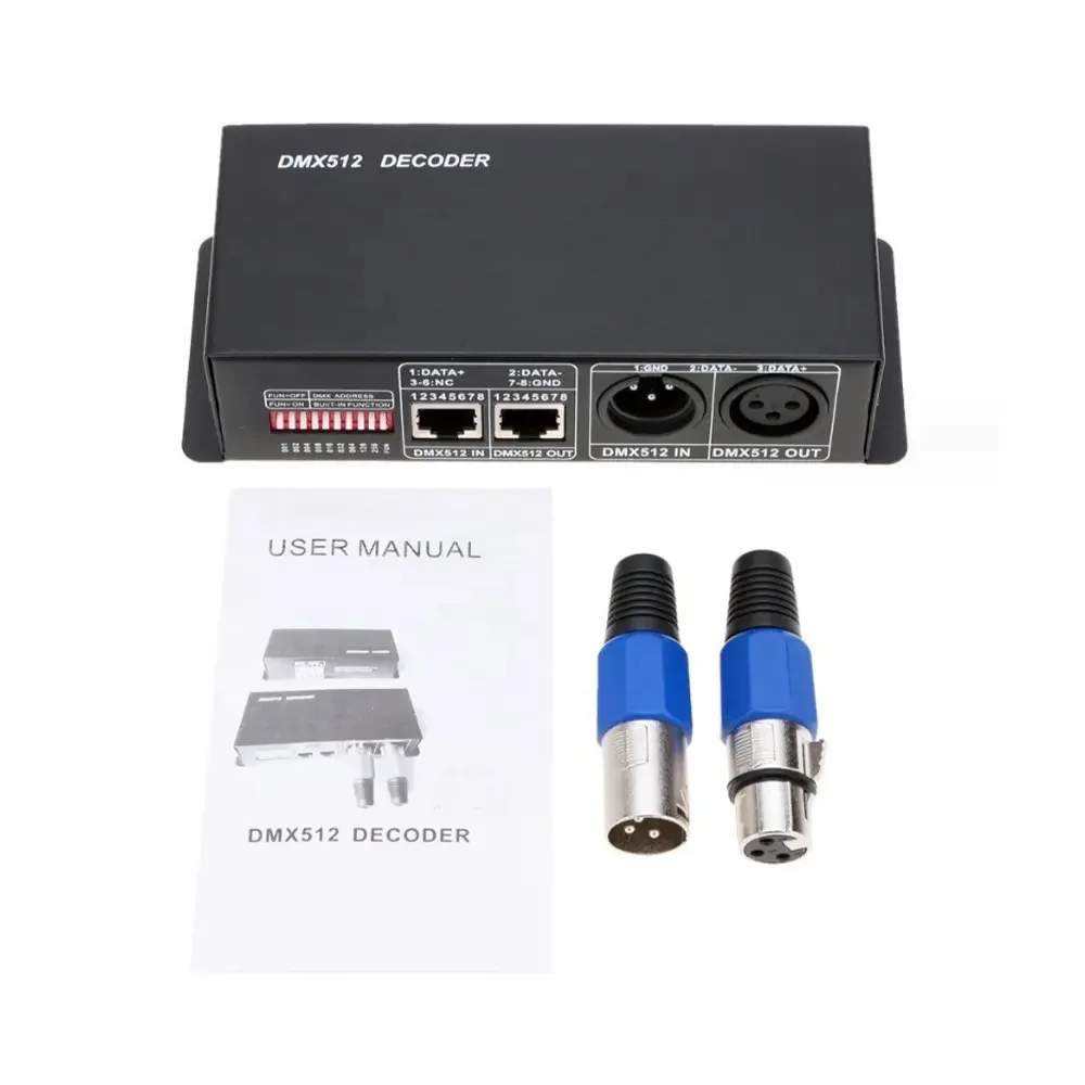
DMX512 декодер RGB RGBW контроллер 3CH 4CH аксессуары для ленточного света DC12V 24V
371,94 ₽ - 492,28 ₽
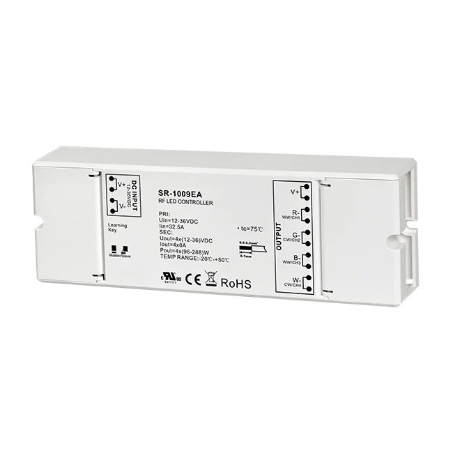
Sunricher 4CH 8A контроллер постоянного напряжения для многоцветного освещения

EV4-D Skydance 12v-60v 4-канальный ретранслятор постоянного напряжения PWM входной сигнал 5A/CH усилитель питания
Новые поступления
Новинки товаров от производителей по оптовым ценам
Светлая Золотая морская солнечная энергия ландшафтное украшение постмодерн минималистский стиль чистая ручная роспись маслом 24x3 1 дюйм/60x80
35-53 $
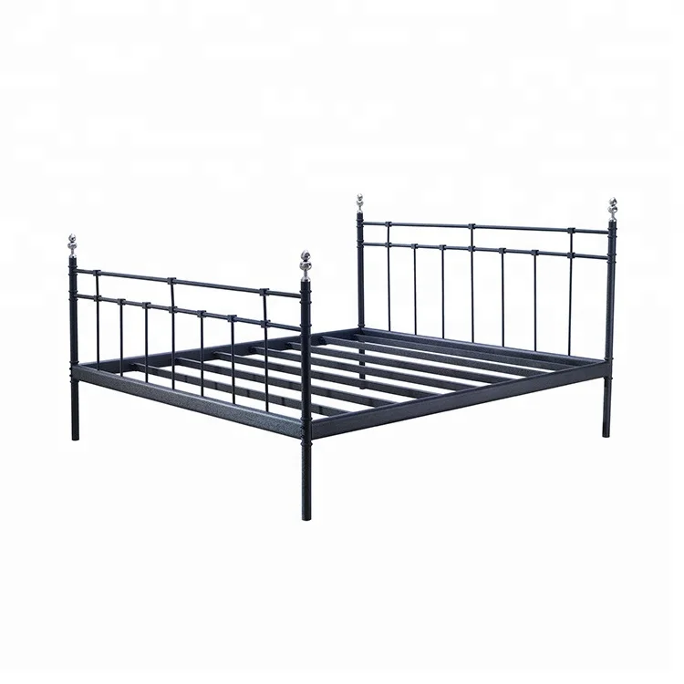
Европейские антикварные простой Последние двойной металлической кровати
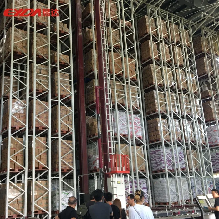
Автоматизированная складская система автоматического хранения в Гуанчжоу Eyda с эффективными стеллажами и
10 000-35 000 $

Декоративный чехол для PS5 Сменный Чехол консоли пластины Playstation5 пылезащитный с защитой от царапин
7,50-7,70 $

Лучшее качество детские подгузники для сухих подгузников новорожденных размер 2 4 и большие доставка или
3 $
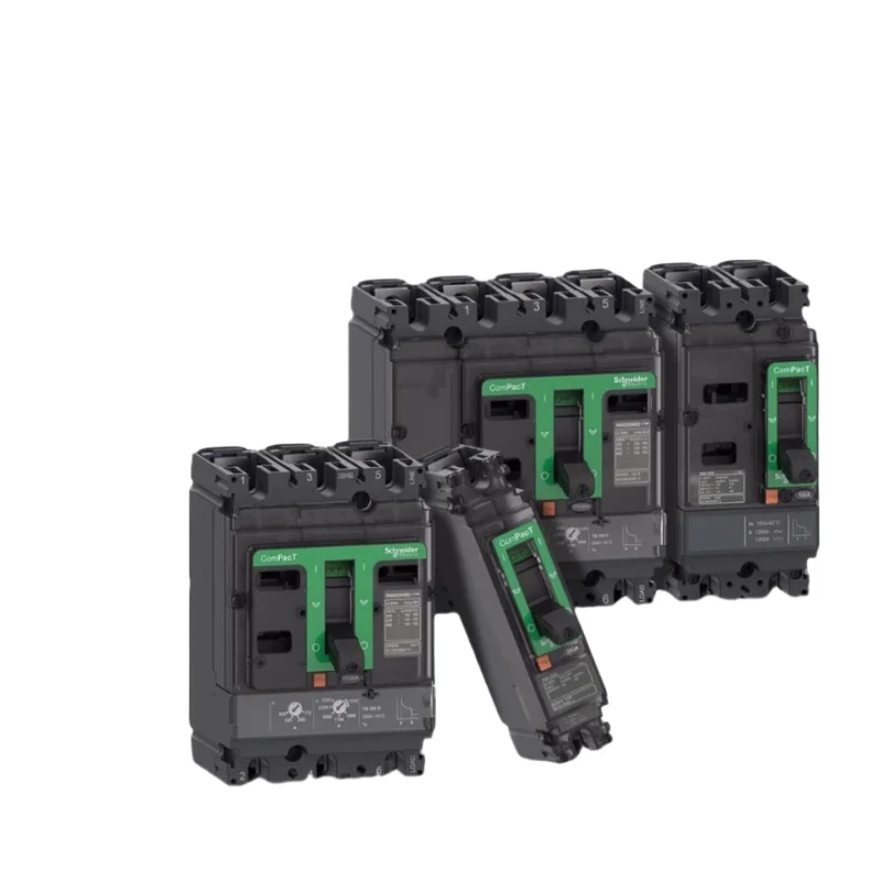
Выключатель для формованного корпуса Schneider NSX100N 50KA AC 3P3D 25A TMD новая модель C10N3TM025
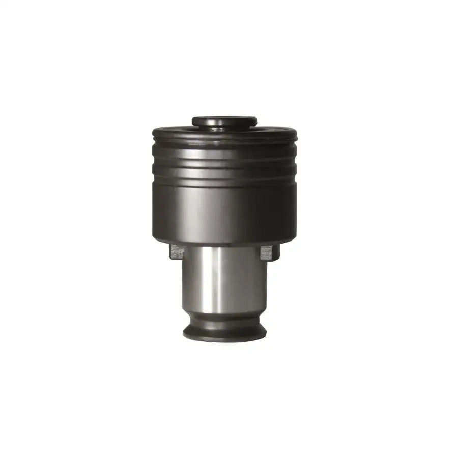
Буф2-.. М .. Краны

Оптовая продажа высококачественный сублимированный клубничный порошок Заводская поставка
5,50-6,40 $