
1500 м CC1120 915 МГц радиочастотный модуль для автоматического считывания измерителя беспроводной ipex ПОЛУПРОДУКТ
- Категория: >>>
- Поставщик: V-Chip Microsystems Inc.
Сохранить в закладки 60745112998:
Описание и отзывы
Характеристики
1500m CC1120 915mhz long distance rf module for automatic meter reading ipex wireless module

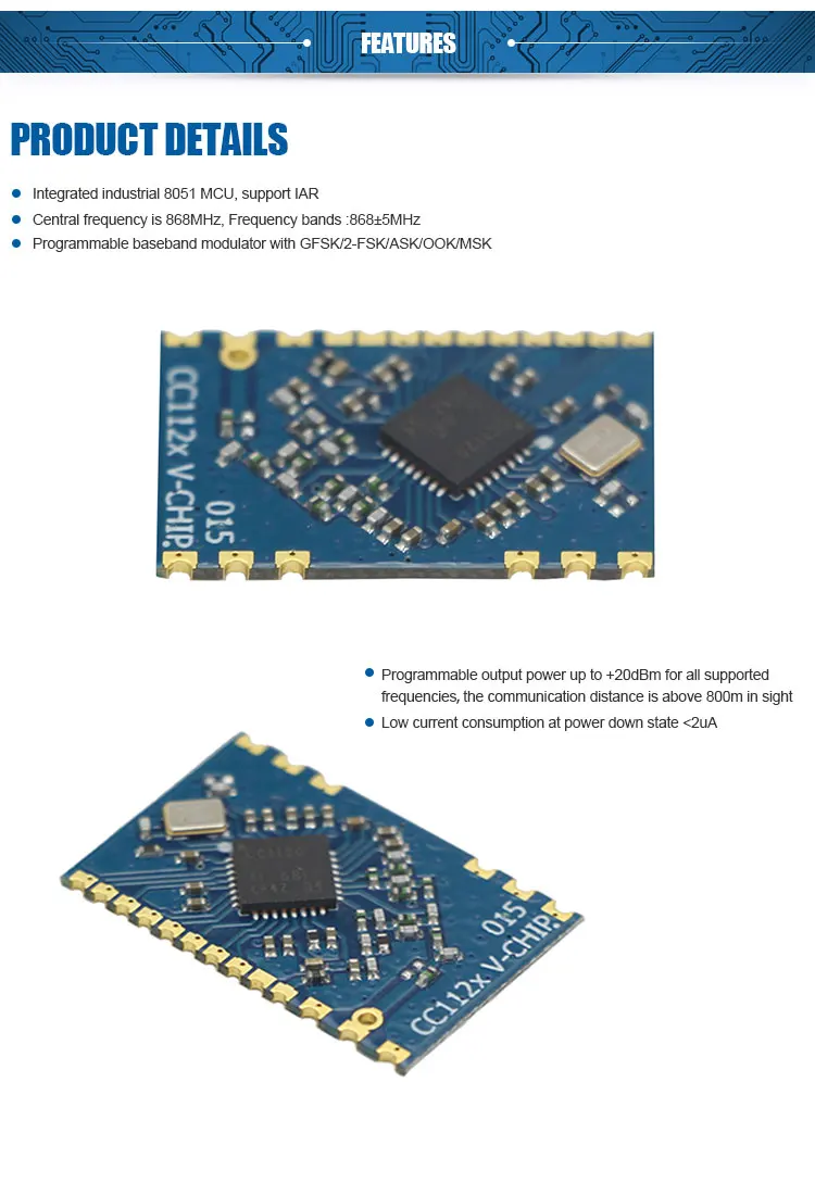
VT-CC1120-915M is based on RF Transceiver CC1120 of TI Chipcon,it’s a small size and ultra low power UHF wireless module. CC1120 is fully integrated single-chip radio transceiver designed for high performance at very low power and low voltage operation in cost effective wireless systems. The circuit is mainly intended for the ISM (Industrial, Scientific and Medical) and SRD (Short Range Device) frequency bands at 164-192 MHz, 410-480 MHz and 820-960 MHz. The MAX RF output power can be set as high as +16dBm, with data rate as high as 200Kbps. The module integrated many RF functions thus you can use it conveniently and reducing your development time.
Detail Parameters

Test operating conditions:Ta=25°C,VCC=3.3V if nothing else stated.
Parameter | Type | Condition/Note |
Operating supply voltage | DC 2.0~3.6V |
|
Frequency range | 820-960MHz | Programmable |
Frequency accuracy | ±10ppm |
|
Modulation format | 2-FSK/4-FSK/2-GFSK/4-FSK/MSK/OOK | Programmable |
Transmit power | -11~+16dBm | Programmable |
TX current consumption | <65mA | Po=16dBm |
Receiver sensitivity | -121dBm | 1.2kbps DEV=4KHz RX BW=25KHz |
RX current consumption | <22mA |
|
Sleep State current consumption | <1uA |
|
Data rate | 0~200Kbps | Programmable |
Communication distance | 1800m | 1.2kbps |
Antenna impedance | 50ohm |
|
Operating temperature | -40~+85 °C |
|
Storage temperature range | -40~+125°C |
|
Dimension | 23.05 mm×15.06 mm×1.8mm | See more in PCB description |
Note:
1. The module transmission data rate will affect Transmission distance ,the higher the data rate , the closer the distance, and the lower the receiving sensitivity.
2. The supply voltage to the module will affect TX power, in the operating supply voltage range, the lower the voltage, the lower the TX power.
3. The module central frequency will change as the operating temperature change, use it under suggest temperature, the module can work well.
4. The antenna will strongly affect the communication distance, please select matched antenna and connect it correctly.
5. The module mount will affect the communication distance.
Features

Related Product

Applications
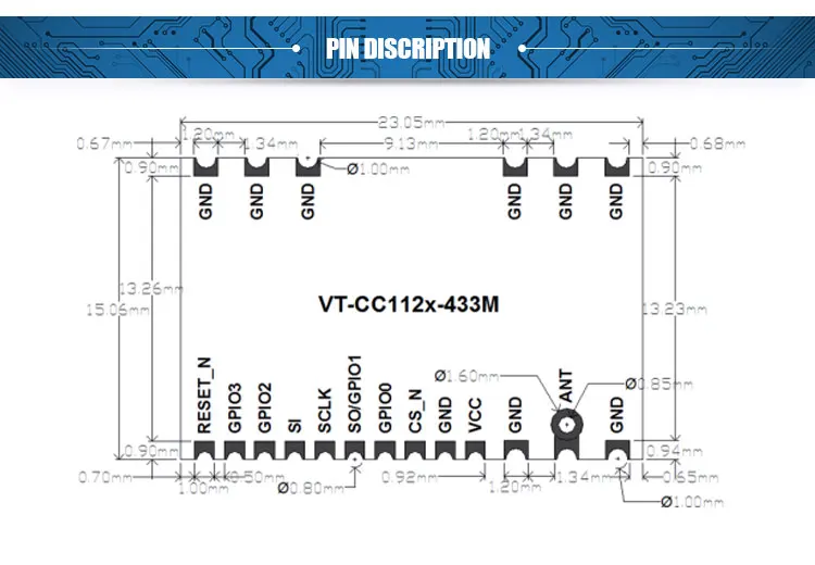
Pin name | Pin type | Description |
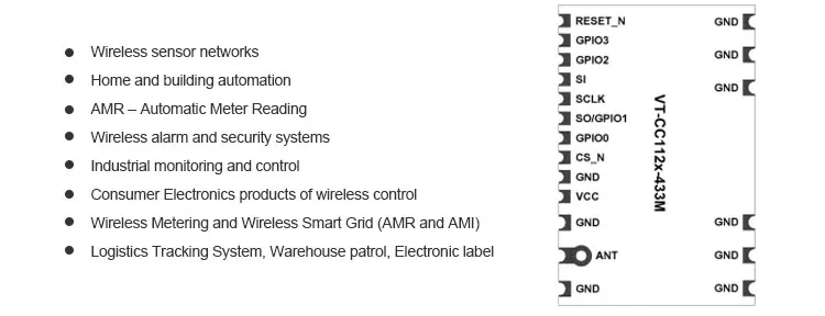
VCC | Power(Analog) | DC 2.0-3.6V power supply |
GND | Ground |
|
CS_N | Digital In | Chip select, active low |
GDIO0 | Digital I/O | Data output,configuration by register |
SO/GPIO1 | Digital I/O | Data output(SPI)or GPIO |
SCLK | Digital In | Clock input(SPI) |
SI | Digital In | Data input(SPI) |
GDIO2 | Digital I/O | Data input/output,configuration by register |
GDIO3 | Digital I/O | Data input/output,configuration by register |
RESET_N | Digital In | Reset,active low |
ANT | Antenna port | Impedance 50ohm |

Note:
The pin sequence above are not the actual pin sequence refer pin description. SPI, I/O interface should connect with the MCU’s I/O pin in order to archive your functions. The circuit must be take ESD protect to prevent damage module. Good RF performance determines on the module position, ground and antenna fixing. Any question about the module please contact with the FAE engineer.
Configuration Registers
The configuration of CC1120 can be done with software SmartRF Studio7. Complete descriptions of the registers are given in the CC1120 datasheet. We can provide evaluation board and demo code to the customer to develop and evaluate the module’s capability.
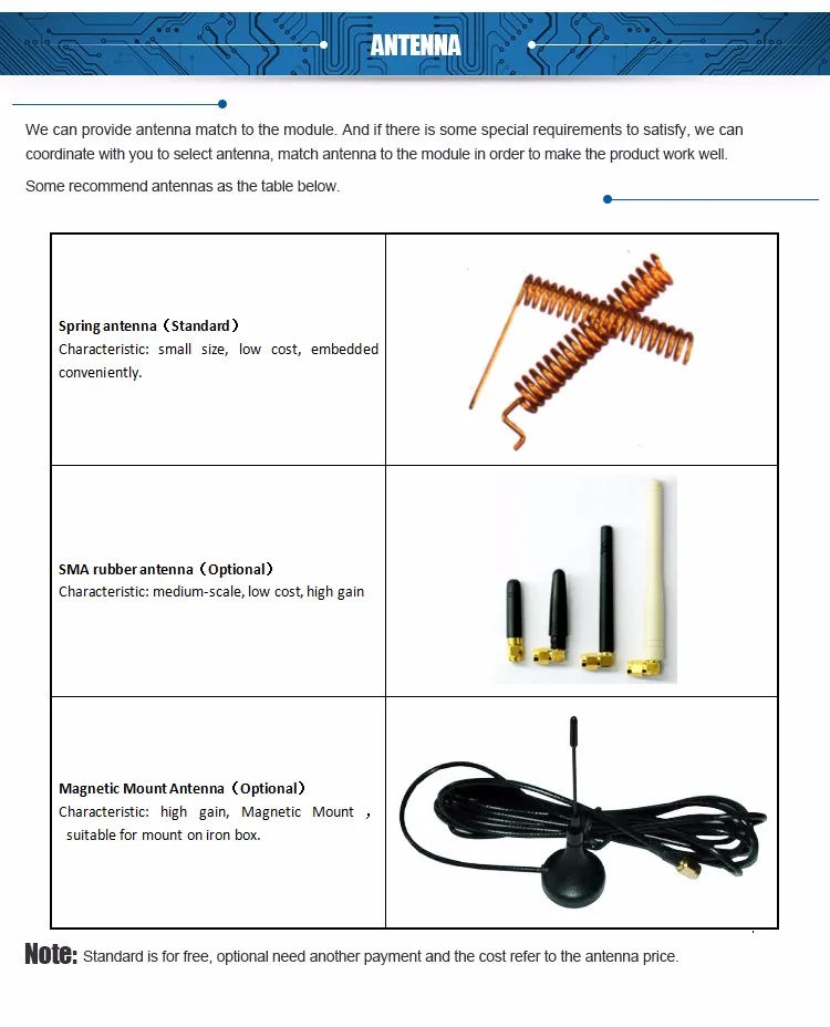
Company Information


Packaging & Shipping

FAQ

Description | Reason and Solution |
Can’t communication | 1.The power supply connect not well, check the module VCC whether it is out of maximum rating. 2.The signal line connect not well, check the module SPI interface. 3.The settings of the transmitter module and receiver module are not the same. Check these modules’ register configuration. 4.Signal block. If the transmitter work with a high TX power, and the receiver was put at a short distance(<0.5m), maybe there is a signal block to make no communication. |
Communication distance is too short | 1.The application environment is too bad or the antenna is shield. Put the antenna to a better place outside or higher throw a coaxial line , replace it with a higher gain antenna. 2.The work space contains a same frequency interference source, or a strong magnetic field interference, power source disturbance. Try to change the carrier frequency or get far away from the source of the disturbance. 3.The power supply is not strong. Check the voltage and the current whether it is enough. |
High data error | 1.The power supply ripple is too big, Change the power supply. 2.Check the module register configuration, it is recommended to set as the CC1120-datasheet. 3.There is a carrier frequency interference, change the channel. 4.The antenna unmatched to the module RF interface, change another matched antenna. |

Похожие товары
Модуль приемопередатчика INKSON BGM220 SMD 31 синий v5.2 RF 2,4 ГГц 2,4835 ГГц BGM220PC22HNA2
Китайский цифровой рулон для рулона цветных чернил, принтер для этикеток для футболок
12 800,00 $
Высококачественный узкий промышленный ремень с V-образным приводом спа SPB SPC SPZ
GRP материал компаунда FRP пластик Smc лист формовочный состав для резервуара для воды септический резервуар
Food grade plastic aluminum laminated plastic film rolls for sachet snack food biscuit packaging
3,18 $ - 3,28 $

Чайный кофе, сахар, 4 шт., металлический ящик для хлеба, контейнер для хранения хлеба, набор канистр
3,30 $ - 3,70 $
Байпас Hilux задняя модель
Новые поступления
Новинки товаров от производителей по оптовым ценам
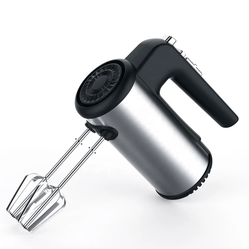
300 Вт безопасный для посудомоечной машины 5-скоростной турбо с крючками для теста, венчик, электрический ручной миксер
571,11-666,30 ₽
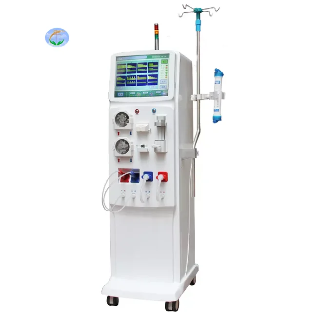
Медицинский портативный прибор для гемодиализа катетер и кровообращения диализа почек ухода за здоровьем
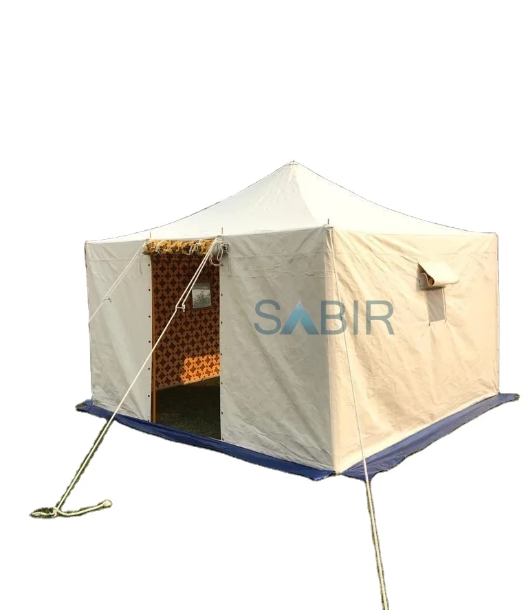
Многофункциональная роскошная водонепроницаемая палатка из брезента для кемпинга однокомнатная всесезонная с настраиваемым размером новый стиль рынка Ближнего Востока
45 688,76-56 159,10 ₽

Санитарно-гигиеническое сиденье для
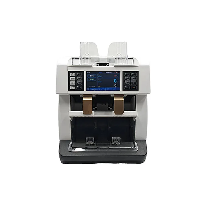
Счетчик купюр с низким уровнем шума на тонкопленочных транзисторах, автоматическое определение разных валют, 4,2 дюйма
50 448-52 351,70 ₽
Ожерелье из нержавеющей стали изящное ожерелье с чакрами на заказ модное позолоченное ювелирное изделие водонепроницаемой подвеской без
121,84-217,03 ₽
Мужские спортивные кроссовки с логотипом
856,67-999,45 ₽
OEM ODM, настоящее изобретение, персонализированный прямой автоматический открытый пользовательский логотип, рекламный зонт для гольфа с логотипом для отелей
842,39-938,53 ₽