

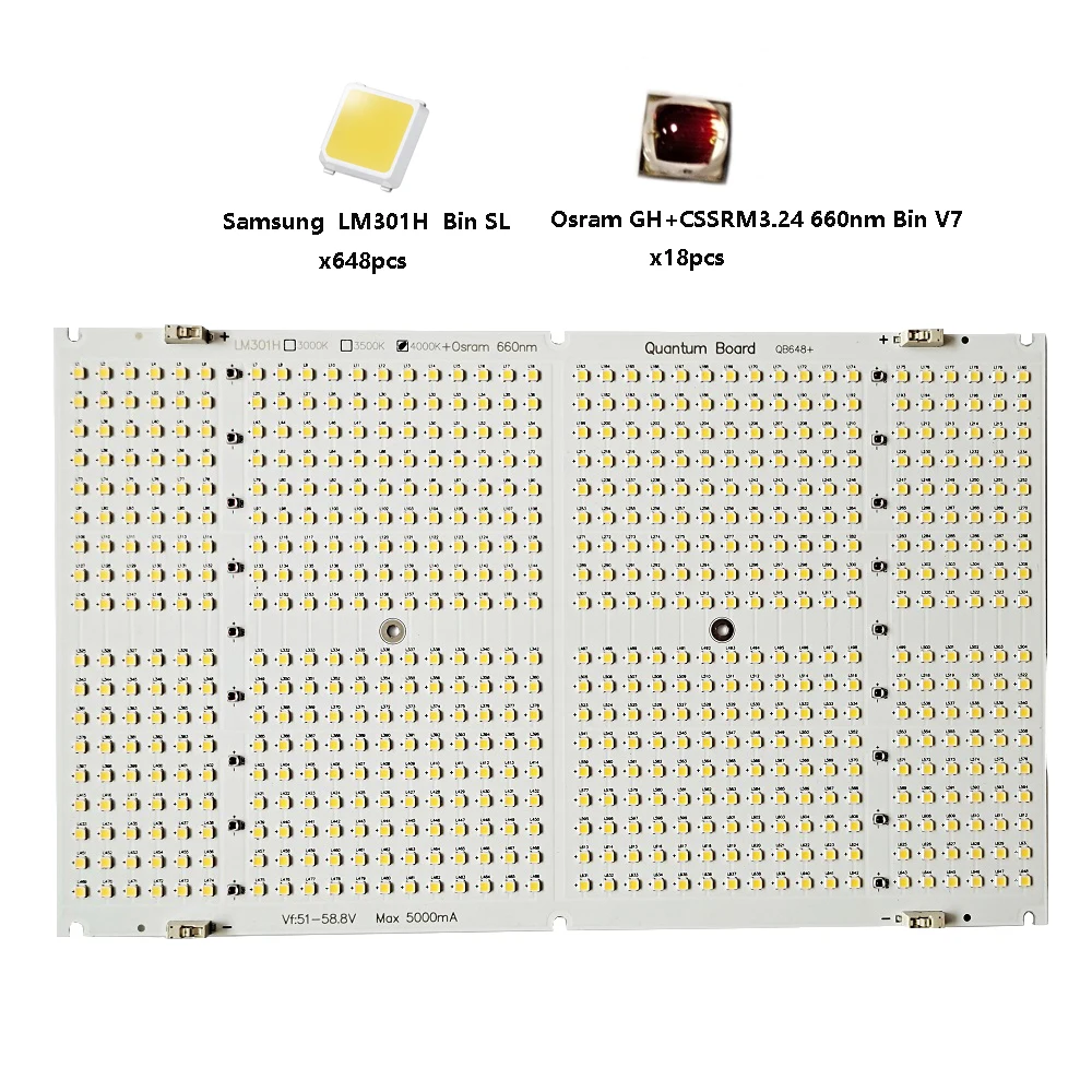
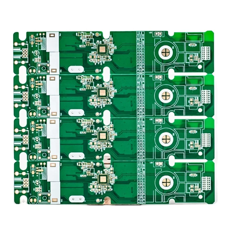
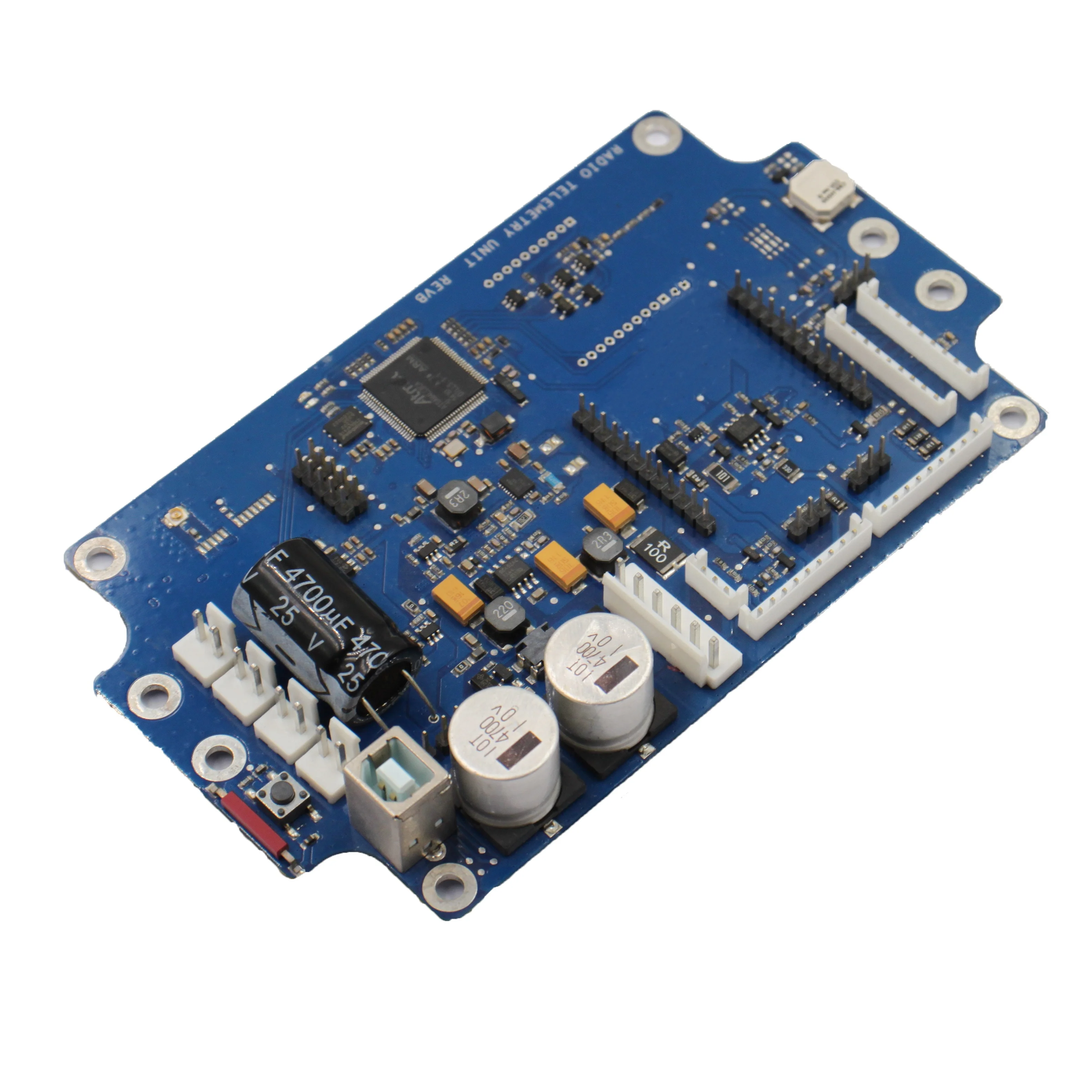
Печатная плата, печатная плата, производство печатных плат, печатная плата на заказ, печатная плата
1,00 $ - 3,00 $


Сохранить в закладки 62230901261:
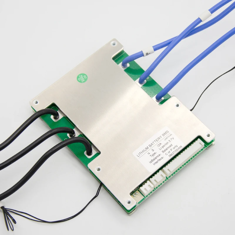
JBD-HP28SA is the hardware BMS which designed for battery packs of the inverter, the electric bicycles and the electric motorcycles of batter packs by Dongguan City Jia Bai Da Electronic Technology Co., Ltd.It can be applied to lithium batteries with different chemical properties, such as lithium ion, Li-polymer. Lithium iron phosphate, etc. The protection board has strong loading capacity and the maximum continuous discharge current can reach 100A.
● 4~16 cell series protection
● Various protection functions for charging and discharging
● Discharge overcurrent, short circuit protection functional processes of hardware
● reserves the discharging control switch and the position of discharging temperature protection,
● Very low static current consumption
● Containing charging equalization function
Application
Battery series | Battery Rated Voltage | Battery series | Battery Rated Voltage | Battery series | Battery Rated Voltage |
4 | 3.6V/3.7V | 7 | 3.6V/3.7V | 10 | 3.6V/3.7V |
3.2V | 8 | 3.2V | 12 | 3.2V | |
13 | 3.6V/3.7V | 14 | 3.6V/3.7V | 16 | 3.6V/3.7V |
3.2V |
Overcharge protection: When the battery is under the charging state, the voltage keeps going up. When the protection board detects that the voltage of any cell is higher than the overcharge protection value, the protection board will start timing immediately. When the time reaches the overcharge protection delay, the protection board will turn off the charging MOS tube, at that time, it cannot be charged.
Overcharge protection recovery: After the overvoltage protection appears on the protection board, the battery voltage will going down under the static or discharge state of the battery. When the protection board detects that each voltage is lower than the recovery voltage of the overcharge protection, the protection board will output a signal and turn on the charging MOS tube to charge.
Over-discharge protection: When the battery is under the discharge state, the voltage keeps going down. When the protection board detects that the voltage of any cell is lower than the overcharge protection value, the protection board will start timing immediately. When the time reaches the over discharge protection delay, the output signal of the protection board will turn off the discharge MOS tube, the load lock circuit will work, but, it cannot discharge at this time.
Over discharge protection recovery: After the over discharge protection appears on the protection board, the battery voltage will going up under the static or discharge state of the battery. When the protection board detects that each voltage is higher than the recovery voltage of the over discharge protection. At this time, disconnect the load or charge, the protection board will output a signal and turn on the charging MOS tube to charge.
Overcurrent protection: When the battery is under the static or discharge state, the current suddenly increases. When the protection board detects that the current reaches the overcurrent protection value, the protection board will start timing at that time. When the current duration in the circuit reaches the overcurrent protection delay time, the output signal of the protection board will turn off the discharge MOS tube, and the load lock circuit will work. At this time, the discharge cannot be conducted.
Overcurrent protection recovery: After the discharge overcurrent protection appears on the protection board, the discharge MOS tube is turned off, and the current in the loop becomes 0. At this time, the load is disconnected or charged, the output signal of the protection board will turn on the discharge MOS tube to discharge.
The test shall be conducted in a room with a temperature of 25±2℃ and a humidity of 65±20%
Functions | Test items | specification | Unit | |||||
Min. | Type | Max. | ||||||
recharging current | - | - | 100 | A | ||||
Discharging current | - | - | 100 | A | ||||
Charging protection | Charger voltage (CC-CV) lifepo4 | Battery series *3.6 | V | |||||
Charger voltage (CC-CV) Li-ion | Battery series *4.2 | V | ||||||
Over-charge protection voltage lifepo4 | 3.600 | 3.650 | 3.700 | V | ||||
Over-charge protection voltage Li-ion | 4.220 | 4.250 | 4.280 | V | ||||
Over-charge protection delay time | 500 | 1000 | 1500 | mS | ||||
Over-charge protection recovery voltage lifepo4 | 3.400 | 3.450 | 3.500 | V | ||||
Over-charge protection recovery voltage Li-ion | 4.140 | 4.180 | 4.230 | V | ||||
Discharge protection | Over-discharge protection voltage lifepo4 | 2.400 | 2.500 | 2.600 | V | |||
Over-discharge protection voltage Li-ion | 2.700 | 2.800 | 2.900 | V | ||||
Over-discharge protection delay time | 50 | 100 | 200 | V | ||||
Over-discharge protection recovery voltage lifepo4 | 2.900 | 3.000 | 3.100 | V | ||||
Over-discharge protection recovery voltage Li-ion | 2.800 | 2.900 | 3.000 | V | ||||
Over-discharge protection recovery condition | Disconnect load or Charging activation | |||||||
Overcurrent protection | Charging overcurrent protection value | _ | _ | _ | A | |||
Charging overcurrent delay | _ | _ | _ | mS | ||||
Charging release adjustment | _ | |||||||
Discharge overcurrent 1 protection current value | 320 | 360 | 400 | A | ||||
Discharge overcurrent 1 protection delay | 50 | 100 | 200 | mS | ||||
Discharge overcurrent protection recovery condition | Disconnect load or Charging activation | |||||||
Short circuit protection | Short circuit protection delay time | 100 | 200 | 300 | uS | |||
Short circuit protection recovery | Disconnect load | |||||||
Balanced turn-on voltage lifepo4 | 3.400 | 3.450 | 3.500 | V | ||||
Balanced turn-on voltage li-ion | 4.170 | 4.190 | 4.220 | V | ||||
Balanced current | 20 | 30 | mA | |||||
Temperature protection(internally installed) | temperature protection value | _ | 75 | _ | ℃ | |||
temperature protection release value | _ | 53 | _ | ℃ | ||||
Internal resistance | Discharge loop internal resistance | _ | 10 | 20 | mR | |||
Self-consuming | Operating mode | _ | 20 | 50 | uA | |||
Working humidity | Normal operating range | -20 | _ | 70 | ℃ | |||
Storage temperature | Humidity<90%, No condensation | -40 | _ | 85 | ℃ | |||
Protection board size | L*W*H | 150*102*15 | mm | |||||
When assembling the wiring, weld the cable and the cell correctly, connect the B- of the PCM with the total negative pole of the cell, and then insert the cable into the needle base on the PCM. (Note: different connection modes for different strings, and different connection modes for the same port)
Новинки товаров от производителей по оптовым ценам