
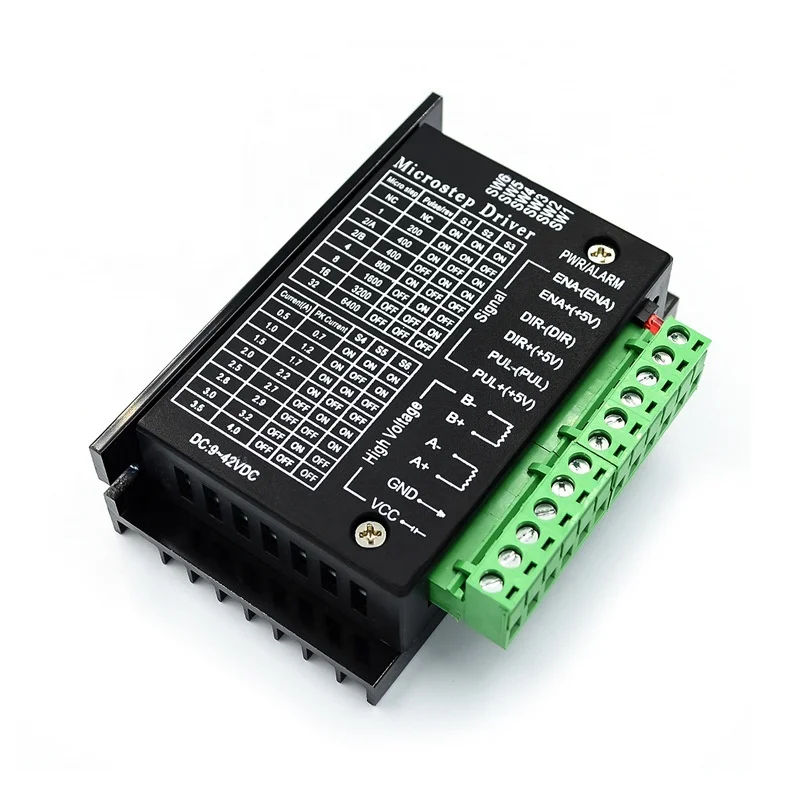
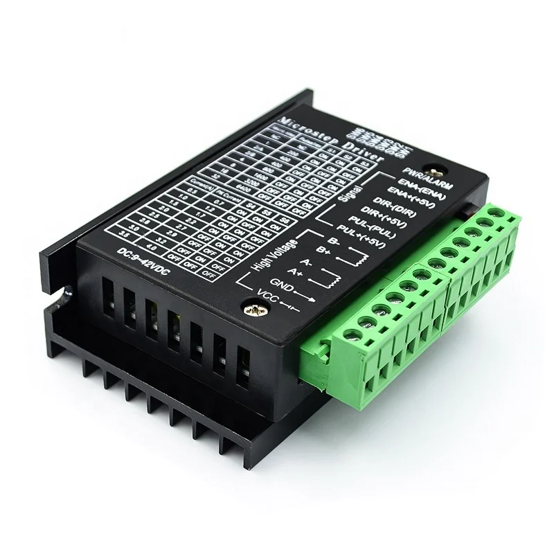
Драйвер шагового двигателя 42/57/86 TB6600, обновленная версия, 32 секции, 4,0 А, 42 в (импульс 3 24 В)
- Category: Motor Driver >>>
- Supplier: Shenzhen Junbaoxiang Technology Co. Ltd.
Share on (1600051135458):
Product Overview
Description
Product Description
TB6600 Specifications:: | ||
This drive is an upgraded version of the TB6600, the breakdown of heightening to 32 segments, for high segmentation purposes. Applicable stepper motor: 42,57,86 type of 2-phase 4-phase (4-wire 6 wire line 8) Features: 1, 9V-42V DC power supply; 2, H-bridge bipolar constant-phase flow-driven; 3, the maximum output current of 4.0A eight optional; 4, up to 32 segments of six kinds of sub-modes available; 5, the input signal is high-speed optical isolation; 6, standard common anode single pulse interface; 7, offline hold function; 8, semi-enclosed chassis can accommodate more demanding environment; 9, provide energy semiautomatic current lock function; 10, built-in thermal protection and overcurrent protection. Packing list : One piece TB6600 stepper motor driver Signal input ⑴CP +: Pulse signal input positive terminal. ⑵CP-: Pulse signal input negative terminal. ⑶DIR +: Positive end of motor forward and reverse control. ⑷DIR-: The negative end of the motor's positive and negative control. ⑸EN +: Positive end of motor offline control. ⑹EN-: Motor off-line control negative terminal. Motor winding connection: ⑴A +: Connect the A + phase of the motor winding. ⑵A-: Connect the A-phase of the motor winding. ⑶B +: Connect B + phase of motor winding. ⑷B-: Connect B-phase of motor winding. Working voltage connection: ⑴VCC: DC power supply is positive (note: 10V < VCC < 42V). ⑵GND: DC power supply is negative. Signal input terminal optocoupler isolation connection method There are two connection methods for the input signal interface: the user can adopt the common anode connection method or the common cathode connection method as needed. 1. Common anode connection method: connect CP +, DIR + and EN + to the power supply of the control system respectively. If the power supply is + 5V, it can be directly connected. If the power supply is greater than + 5V, an external current limiting resistor R must be added. , To ensure that the drive current of 8-15mA is provided to the internal optical coupling of the driver. The pulse input signal is accessed through CP-; at this time, DIR- and EN- are active at low level. 2. Common cathode connection: connect CP-, DIR-, EN- to the ground terminal of the control system (SGND, isolated from the power ground); the + 5V pulse input signal is added through CP +; at this time, DIR +, EN + are in Active high. The connection value of the current limiting resistor R is the same as the common anode connection method. | ||
Packing&Shipping


Contact details

Company Introduction
Shenzhen Junbaoxiang Electronic Tech Co.,Ltd, based in Hongkong and HQ in Shenzhen, specialize in nearly all kinds of electronic components like IC, Transistor, Diode, Capacitor, Resistor etc and pcba. We cooperated with thousands of customers all over the world, most of them came from Europe and Asia. After years of development, we got exellent reputation and also keep huge stock .


FAQ
Q: Is your parts new and original ?
A: Yes !Our parts could accept any kinds of testing , if there is any quality problems we will take responsible .
Q: What is your warranty ?
A: Within 60 days after package have been received .
Q: How to pay the order ?
A: We could accept TT , Escrow , Paypal , Western Union and Alipay .After the order have been confirmed the invoice will be sent
for reference .Then make payment as the way you like , as soon as the payment have been confirmed ,we will arrange shippment
within 3 days .
Q: If product has problems ?
A: If there is any quality problems or questions , we could offer technical support or return service .
Q: What is your lead time ?
A: There are no lead times for in-stock products. Most of the parts could be shipped out within 3 days after payment have been
confirmed.
We Recommend


DC24 10A RS485 CAN DC Servo Motor Driver For Speed Gate Turnstile
US $274.00-$322.00

2021 New Wholesale Ac Servo Motor 400w Corona Servo Extension
US $330.00-$630.00


New Arrivals
New products from manufacturers at wholesale prices


