
3 phase factory 220vac DVS3422 stepper motor drive for cnc kit
- Category: Motor Driver >>>
- Supplier: Shenzhen DVS Mechatronics Co. Ltd.
Share on (60228482093):
Product Overview
Description
3 phase factory 220vac DVS3422 stepper motor drive for cnc kit
stepper motor drive


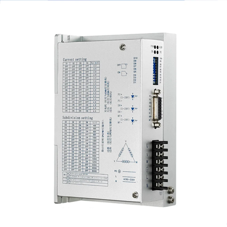
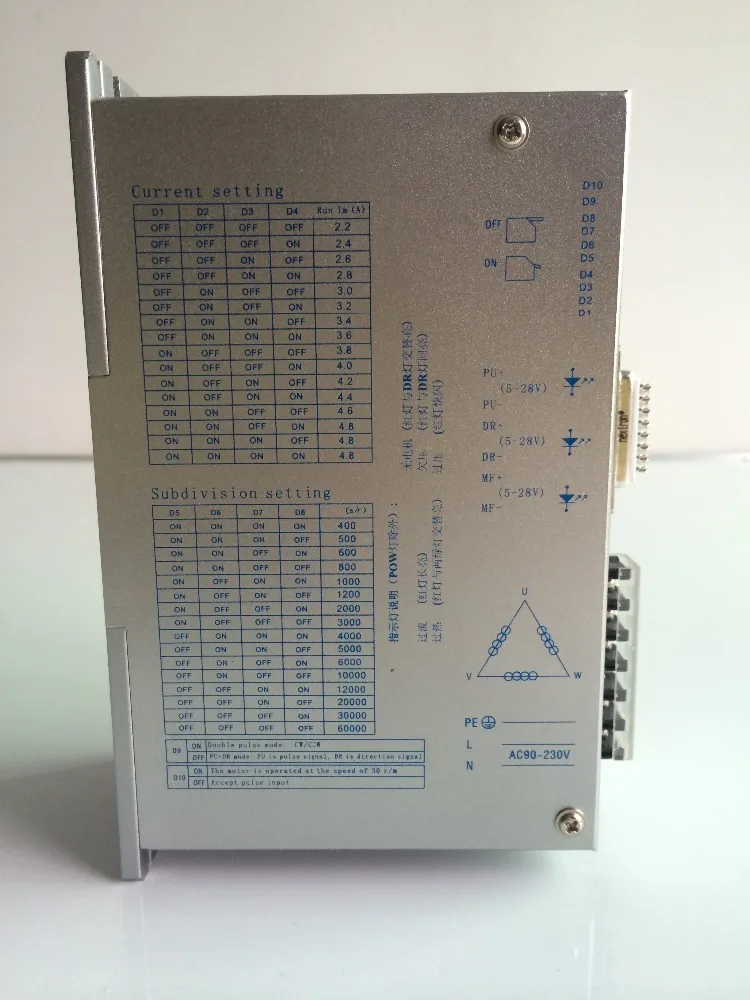
DVS3422 is full digital 3 phase stepper motor drive based on advanced DSP control. Designed and Produced by marketing demands. The circuit that it adopts is similar to the circuit of servo control which enables the motor run smoothly without noise and vibration. The voltage ranges from 120V to 260VAC. It is designed for use with the 3 phase hybrid stepper motor of all kinds with 57mm to 130mm outsider diameter, related phase current from 2.2A to 4.8A.
♦ 16 channels constant angle, constant torque mircsteps,upmost microstep: 60000ppr
High response frequency: 200Kpps
♦ Current of winding will be reduced by approximately 50% when no step pulse command is received for 1.5 seconds.
♦ Opto-isolated signal I/O
♦ Drive current is adjustable in 16 channels from 2.2A/phase to 4.8A/phase
♦ Single power supply from 120V to 260VAC
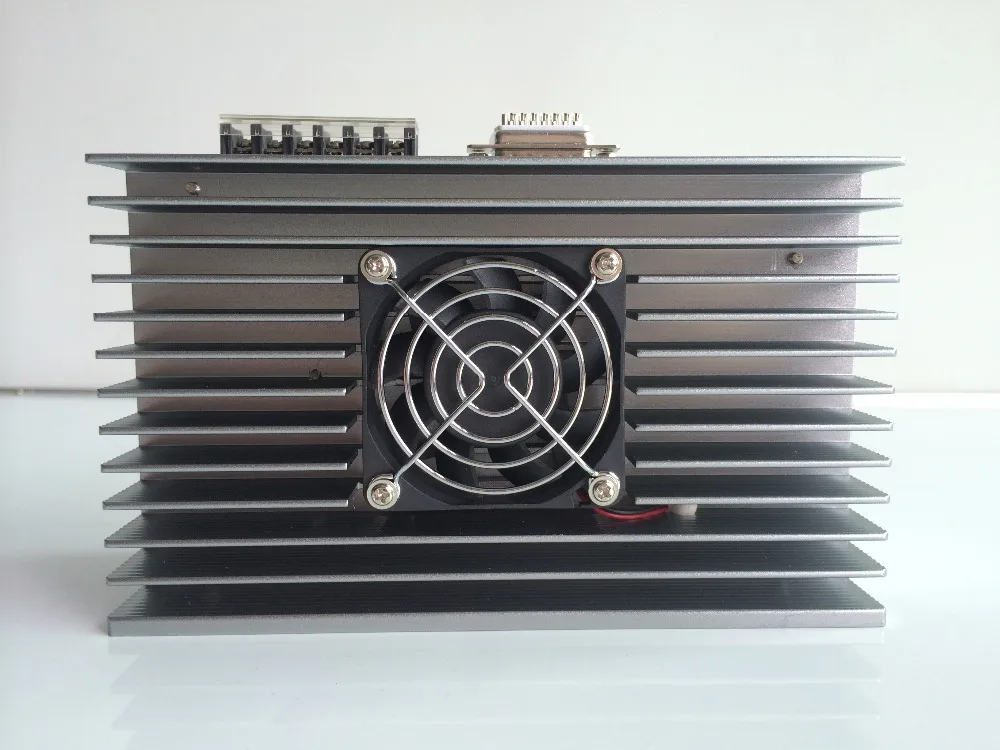
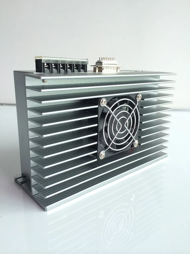
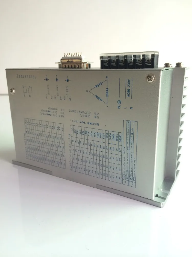
♦ Dimension: 178*67*108mm3 Net Weight: 1kg

DVS 3 4 22
A B C D
A DVS: DVS Brand Motor Drive
B Output Phase: 3 Phase
C Max Output Current: 4.8A
D Rated Input Voltage: 220V
Notice: The max input voltage has been improved to 260V


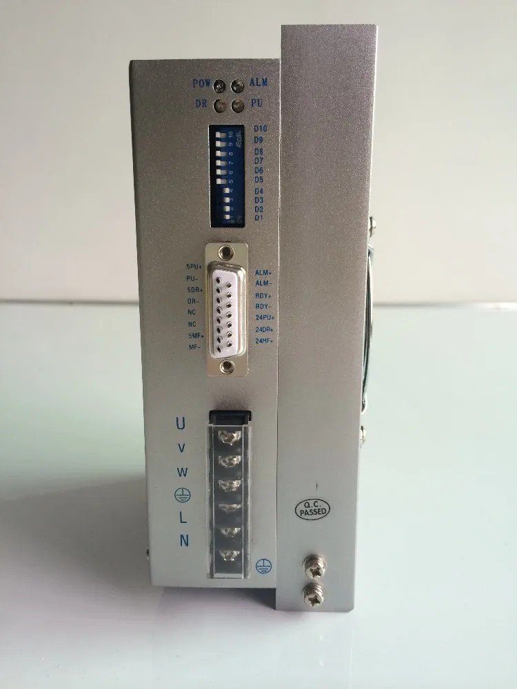
| Symbol | Function | Definition |
| 5PU+ | Positive of opto-isolated input signal | Connect to +5V power supply,drive voltage ranges from +5V to +24V.Current limiting resistance is needed when it is over +5V. |
| PU- | DP9=OFF,PU is step pulse signal | With the falling edge of the signal PU, the motor execute an angular step. The input resistance is 220Ω. Low voltage 0-0.5V,high voltage 4-5V,pulse width>2.5μs. |
| DP9=ON,PU is positive step pulse signal | ||
| 5DR+ | Positive of opto-isolated input signal | Connect to +5V power supply,drive voltage ranges from +5V to +24V.Current limiting resistance is needed when it is over +5V. |
| DR- | DP9=OFF,PU is step pulse signal | Change the motor's direction of rotation. The input resistance is 220Ω. Low voltage 0-0.5V,high voltage 4-5V,pulse width>2.5μs. |
| DP9=ON,PU is nagtive step pulse signal | ||
| 5MF+ | Positive of opto-isolated input signal | Connect to +5V power supply,drive voltage ranges from +5V to +24V.Current limiting resistance is needed when it is over +5V. |
| MF- | Motor free signal | The motor current will be cut off and the driver stops working when it is effective. |
| ALM+ | Positive of opto-isolated input signal | The signal is effective(low voltage) when the drive is overcurrent and overheat. |
| ALM- | Negative of opto-isolated input signal | |
| RDY+ | Positive of opto-isolated input signal | It is effective(low voltage) when the driver is ready for receiving controller's signal. |
| RDY- | Negative of opto-isolated input signal | |
| 24PU+ | Positive of opto-isolated input signal | Drive voltage : +24V |
| 24DR+ | ||
| 24MF+ | ||
| L,N | Power supply | 120-260VAC |
| PE | Ground | Ground terminal |
| U | Connection |  |
| V | ||
| W |


¤ Subdivision can be set by your requirement.


Key words : hybrid stepper driver , ac stepper motor drive, 3 phase ac stepper motor drive
We Recommend


DC24 10A RS485 CAN DC Servo Motor Driver For Speed Gate Turnstile
US $274.00-$322.00

2021 New Wholesale Ac Servo Motor 400w Corona Servo Extension
US $330.00-$630.00


New Arrivals
New products from manufacturers at wholesale prices


