cheap price 150 ton portable hydraulic track link pin press
US $350.00-$850.00
Share on (60354028631):

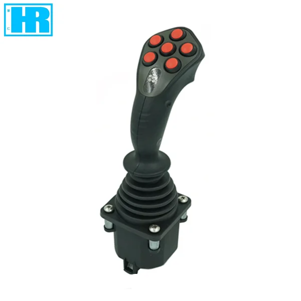
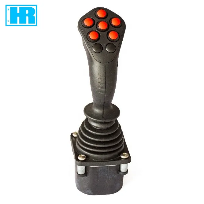
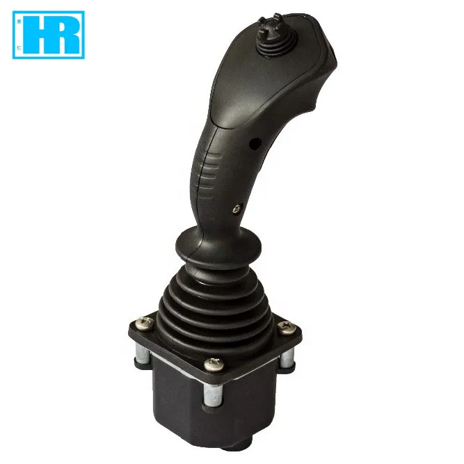
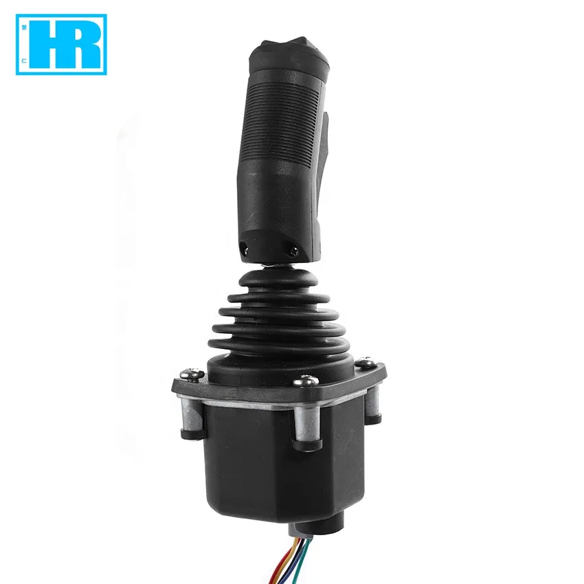
Ergonomics design on mobile application | ||||||||
Uncontact hall effect and long expect-life potentiometer optional | ||||||||
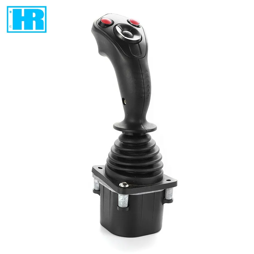
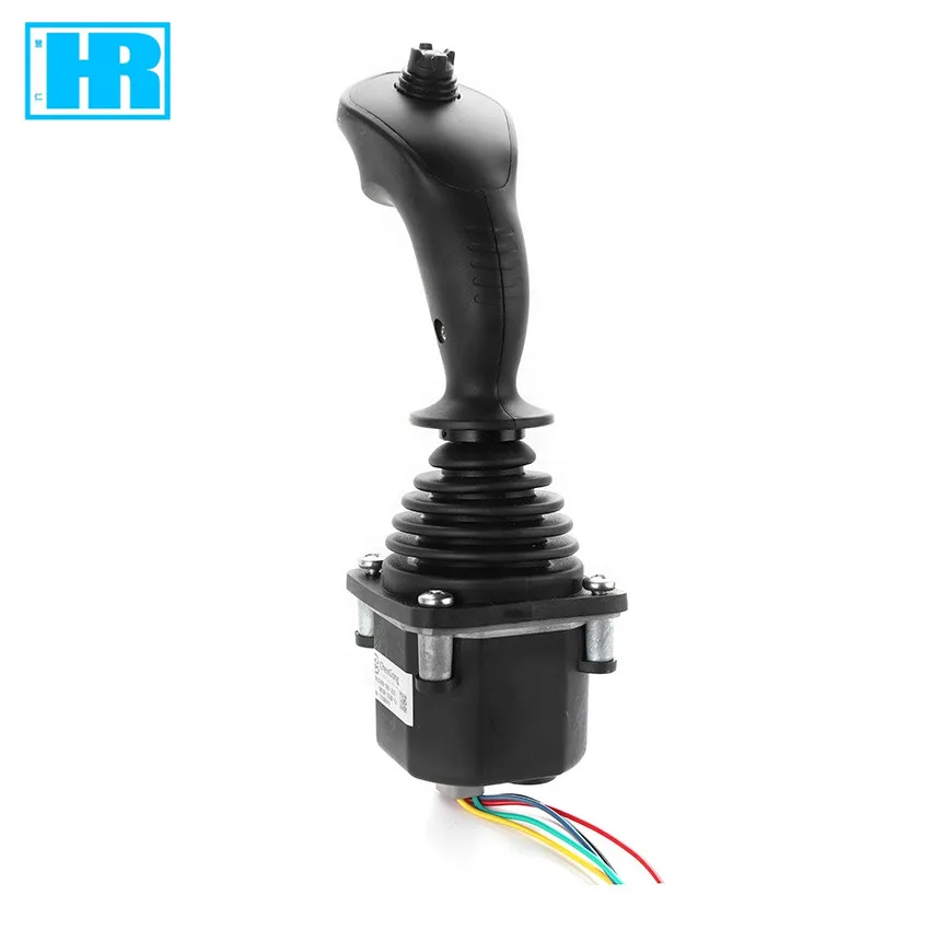
Various handle, different number and location of button switches optional | ||||||||
CAN bus output optional | ||||||||
Typical application on Cranes, loaders, Forklifts, excavators, access platform, tractors, harvesters. | ||||||||
Technical Information | ||||||||
Mechanical features | ||||||||
Travel angle | ±20º | |||||||
Operating type | Automatic Spring return | |||||||
Breakout force | 5N | |||||||
Operating force (max) | 11N | |||||||
Maximum allowable force | >300N | |||||||
Expecting life | >2 million cycles (Potentiometer) | >5 million cycles (Hall effect) | ||||||
Weight | Weight | 475g (Without handle) | ||||||
Electrical parameters | ||||||||
Potentiometer type | ||||||||
Power supply | <36Vdc | |||||||
Resistance | 2KΩ or 5KΩ or 10KΩ | |||||||
Electrical angle | ±18° | |||||||
Center voltage | 48%~52% (percentage of power supply) | |||||||
Center tap angle | ±2.5° | |||||||
On-load voltage (max) | 32Vdc | |||||||
Power dissipation (max) | 0.25W | |||||||
Hall type | ||||||||
Power supply | 5.0±0.5Vdc | |||||||
Supply current | <11mA (Each of hall sensor) | |||||||
Maximum allowable overload voltage | 20Vdc | |||||||
Reverse maximum allowable voltage | -10Vdc | |||||||
Output linearity tolerance | <±0.2V | |||||||
Directional switch | ||||||||
Load capacity | 2mA@30Vdc (Resistance load) | |||||||
Breakout angle | ±5° | |||||||
Contact resistance | <200Ω | |||||||
With electronic amplifier | ||||||||
Power supply | 18~36Vdc (U21~U24) | 9~36Vdc (I21~I22) | ||||||
Power current consumption | <20mA | |||||||
Maximum output current | 10mA (With standard voltage output) | |||||||
Can Bus type | ||||||||
Power supply | 9~36Vdc | |||||||
CAN Version | CAN 2.0B | |||||||
Protocol | J1939 | |||||||
Connector | 6 p-pin (Deutsch,DTM04-6P) | |||||||
Microswitch | ||||||||
Load capacity | 4A@30Vdc (Resistance load) | |||||||
Expecting life | 30 million times (Mechanical) | 200 thousand times (Electrical) | ||||||
Insulation resistance | >100MΩ (500Vdc Insulating-resistance meter) | |||||||
Breakout angle | ±3°~±5° | |||||||
Environmental parameters | ||||||||
Operating temperature | -30℃~+70℃ | |||||||
Storage temperature | -40℃~+85℃ | |||||||
Protection level | IP65 (Above the flange) | |||||||
Description | ||||||||
① Product type | ||||||||
HJ60 series joystick, spring return, installation dimension 61mm*61mm | ||||||||
② Operating type | ||||||||
1A | Spring return, single-axis forward and backward directional operated | |||||||
2AP | Spring return, dual-axis cross directional operated | |||||||
2AC | Spring return, dual-axis arbitrary directional operated | |||||||
③selection of spring | ||||||||
L | Light spring, breakout force4.5N,operating force 9N | |||||||
M | Medium spring, breakout force5N,operating force 11N(standard) | |||||||
H | Heavy spring, breakout force9N,operating force 19N | |||||||
④Output signal | ||||||||
P021* | Potentiometer,<36Vdc power supply, with 2KΩ center-tapped potentiometer,0%-100%Vdc output | |||||||
P022 | Potentiometer,<36Vdc power supply, with 2KΩ center-tapped potentiometer,10%-90%Vdc output | |||||||
P023* | Potentiometer,<36Vdc power supply, with 2KΩ center-tapped potentiometer,25%-75%Vdc output | |||||||
P051 | Potentiometer,<36Vdc power supply, with 5KΩ center-tapped potentiometer,0%-100%Vdc output | |||||||
P052 | Potentiometer,<36Vdc power supply, with 5KΩ center-tapped potentiometer,10%-90%Vdc output | |||||||
P053 | Potentiometer,<36Vdc power supply, with 5KΩ center-tapped potentiometer,25%-75%Vdc output | |||||||
P101 | Potentiometer,<36Vdc power supply, with 10KΩ center-tapped potentiometer,0%-100%Vdc output | |||||||
P102 | Potentiometer,<36Vdc power supply, with 10KΩ center-tapped potentiometer,10%-90%Vdc output | |||||||
P103 | Potentiometer,<36Vdc power supply, with 10KΩ center-tapped potentiometer,25%-75%Vdc output | |||||||
H51 | Hall effect, each axis of single hall sensor,5Vdc power supply,0.5~2.5~4.5V output voltage | |||||||
H52 | Hall effect, each axis of single hall sensor,5Vdc power supply,0~2.5~5.0V output voltage | |||||||
H53 | Hall effect, each axis of single hall sensor,5Vdc power supply,1.25~2.5~3.75V output voltage | |||||||
H54 | Hall effect, each axis of single hall sensor,5Vdc power supply,1.0~2.5~4.0V output voltage | |||||||
H55 | Hall effect, each axis of single hall sensor,5Vdc power supply,1.15~2.5~3.85V output voltage | |||||||
2H51 | Hall effect, each axis of redundant hall sensor,5Vdc power supply,0.5~2.5~4.5V output voltage | |||||||
2H52 | Hall effect, each axis of redundant hall sensor,5Vdc power supply,0~2.5~5.0V output voltage | |||||||
2H53 | Hall effect, each axis of redundant hall sensor,5Vdc power supply,1.25~2.5~3.75V output voltage | |||||||
2H54 | Hall effect, each axis of redundant hall sensor,5Vdc power supply,1.0~2.5~4.0V output voltage | |||||||
2H55 | Hall effect, each axis of redundant hall sensor,5Vdc power supply,1.15~2.5~3.85V output voltage | |||||||
U21 | With electronic amplifier,18-36Vdc power supply,-10V-0V-+10V output voltage | |||||||
U22 | With electronic amplifier,18-36Vdc power supply,+10V-0V-+10V output voltage | |||||||
U23 | With electronic amplifier,18-36Vdc power supply,-5V-0V-+5V output voltage | |||||||
U24 | With electronic amplifier,18-36Vdc power supply,+5V-0V-+5V output voltage | |||||||
I21 | With electronic amplifier,9-36Vdc power supply,2-wire system 4mA -12mA-20mA output current | |||||||
I22 | With electronic amplifier,9-36Vdc power supply,2-wite system 20mA -4mA-20mA output current | |||||||
J33 | CAN bus output ,9-36Vdc power supply Can 2.0B output, source address 33 | |||||||
J34 | CAN bus output ,9-36Vdc power supply Can 2.0B output, source address 34 | |||||||
J35 | CAN bus output ,9-36Vdc power supply Can 2.0B output, source address 35 | |||||||
J36 | CAN bus output ,9-36Vdc power supply Can 2.0B output, source address 36 | |||||||
NA | Without analog signal output | |||||||
The option with * is custom made | ||||||||
⑤ Microswitch (not available for CAN bus output) | ||||||||
MS00 | Without microswitch | |||||||
MS12 | With 4A before and after microswitch (not available for dual-axis cross directional operated) | |||||||
⑥ Handle | ||||||||
HA | HA type handle, top without button | |||||||
HAS | HAS type handle, top with button | |||||||
HD | HD type handle, top without button | |||||||
HDS | HDS type handle, top with button | |||||||
HDR | HDR type handle, top with rocker switch | |||||||
KGDN | KG type handle, with deadman switch, without rocker switch | |||||||
KGDR | KG type handle, without deadman switch and rocker switch | |||||||
SS | See SS page | |||||||
⑦Connection | ||||||||
D | Deutsch connector (only available for CAN bus output) | |||||||
A | AMP connector | |||||||


AMP connector | ||||||
Connector | Pin | Potentiometer | Hall effect | |||
16 ways connector | 1 | Y-axis forward directional switch | Button switch 4 | |||
2 | N/A | Button switch 3 | ||||
3 | X -axis pot left terminal | Button switch 2 | ||||
4 | X-axis pot wiper | Button switch 1 | ||||
5 | X-axis pot right terminal | Top switch | ||||
6 | X -axis pot center tap | Button switch 5 | ||||
7 | X-axis switch common terminal | Button switch 6 | ||||
8 | X-axis left directional switch | Deadman switch | ||||
9 | Y-axis pot backward terminal | N/A | ||||
10 | Y-axis pot wiper | N/A | ||||
11 | Y-axis pot forward terminal | Common terminal of button switch | ||||
12 | Y-axis pot center tap | Deadman switch | ||||
13 | Y-axis switch common terminal | N/A | ||||
14 | Y-axis backward directional switch | N/A | ||||
15 | X-axis right directional switch | N/A | ||||
16 | N/A | N/A | ||||
connector | 1 | Button switch 4 | +5V power supply (hall effect sensor 3&4) | |||
2 | Button switch 3 | 0V power supply (hall effect sensor 3&4)) | ||||
3 | Button switch 2 | +5V power supply (hall effect sensor 1&2) | ||||
4 | Button switch 1 | 0V power supply (hall effect sensor 1&2) | ||||
5 | Top switch | Y-axis output (hall effect sensor 3) | ||||
6 | Button switch 5 | X-axis output (hall effect sensor 2) | ||||
7 | Button switch 6 | X-axis output (hall effect sensor 4) | ||||
8 | Deadman switch | Y-axis output (hall effect sensor 1) | ||||
9 | N/A | N/A | ||||
10 | N/A | N/A | ||||
11 | Button switch common terminal | N/A | ||||
12 | Deadman switch | N/A | ||||
connector | 1 | Secondary Y-axis pot forward | Forward directional microswitch common terminal | |||
2 | Secondary Y-axis pot center tap | Forward directional microswitch common terminal | ||||
3 | Secondary Y-axis pot wiper | Backward directional microswitch output terminal | ||||
4 | Secondary Y-axis pot backward | Backward directional microswitch common terminal | ||||
5 | Secondary X-axis pot left | Left directional microswitch common terminal | ||||
6 | Secondary X-axis pot wiper | Left directional microswitch output terminal | ||||
7 | Secondary X-axis pot center tap | Right directional microswitch output terminal | ||||
8 | Secondary X-axis pot right | Right directional microswitch common terminal | ||||
The wiring diagram is only applicable to the SS handle, the wiring diagram of other types handles with the goods issue. | ||||||




New products from manufacturers at wholesale prices