
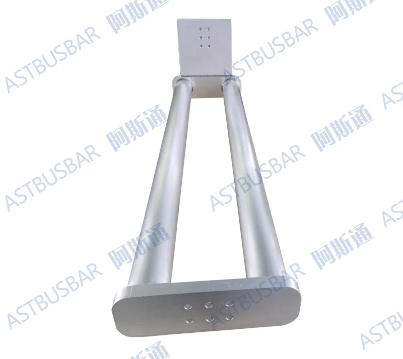
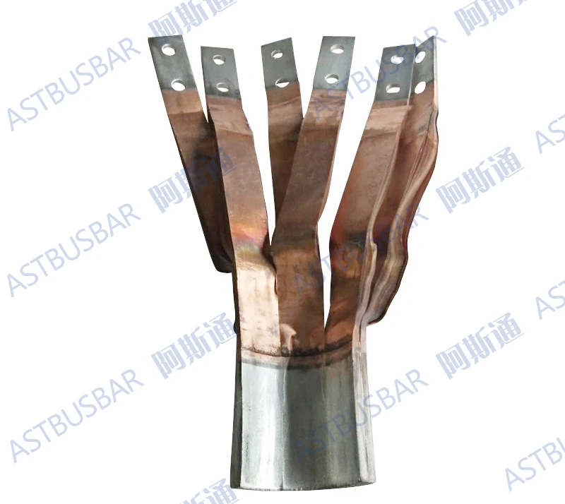
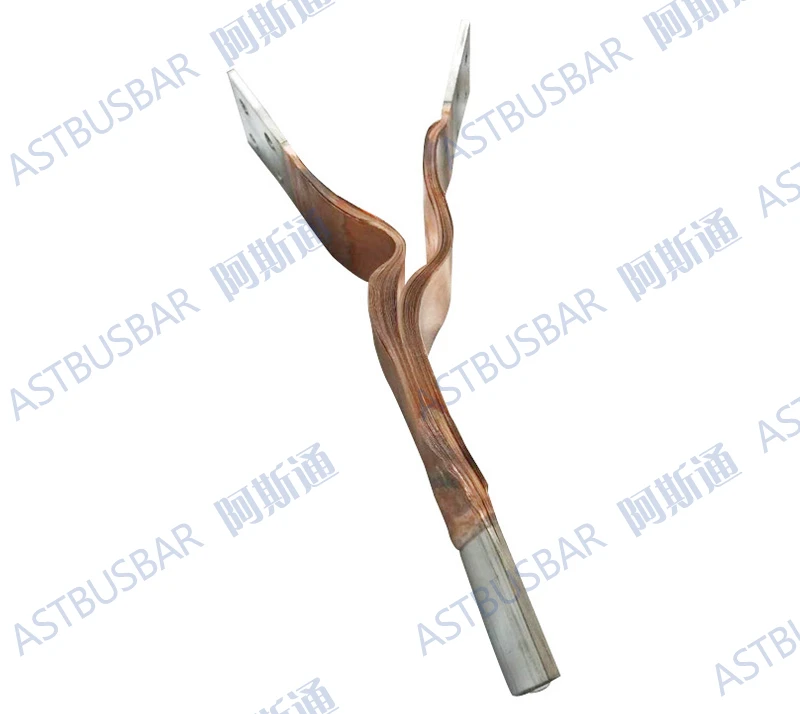
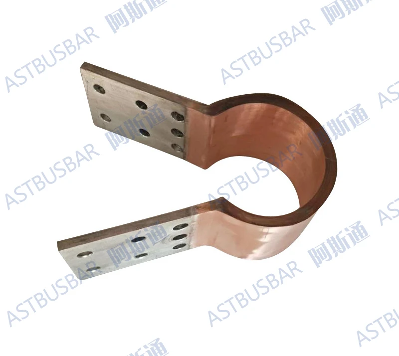
SPECIAL customized flexible copper connectors for tubular busbar
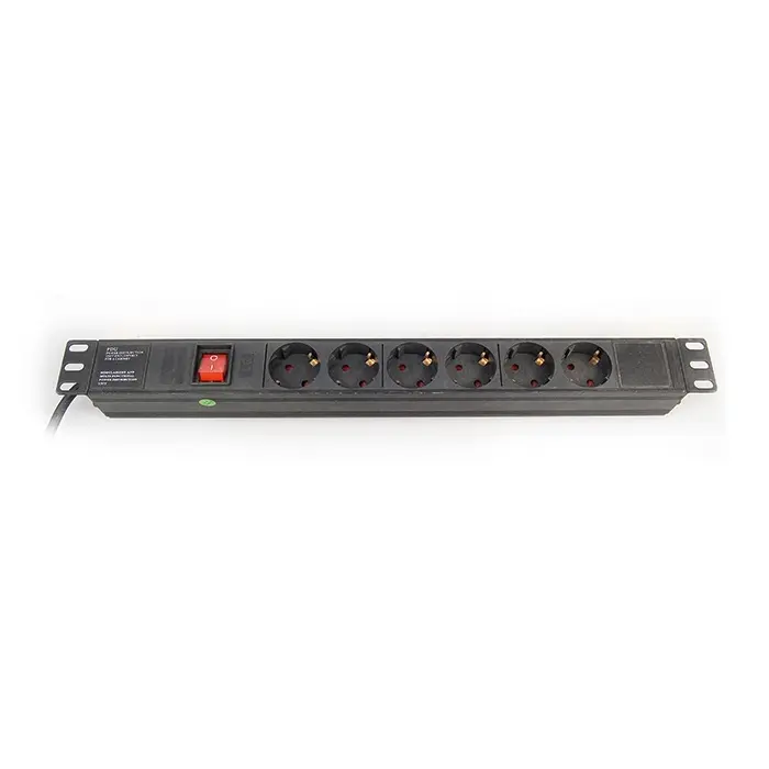
- Category: Power Distribution Equipment >>>
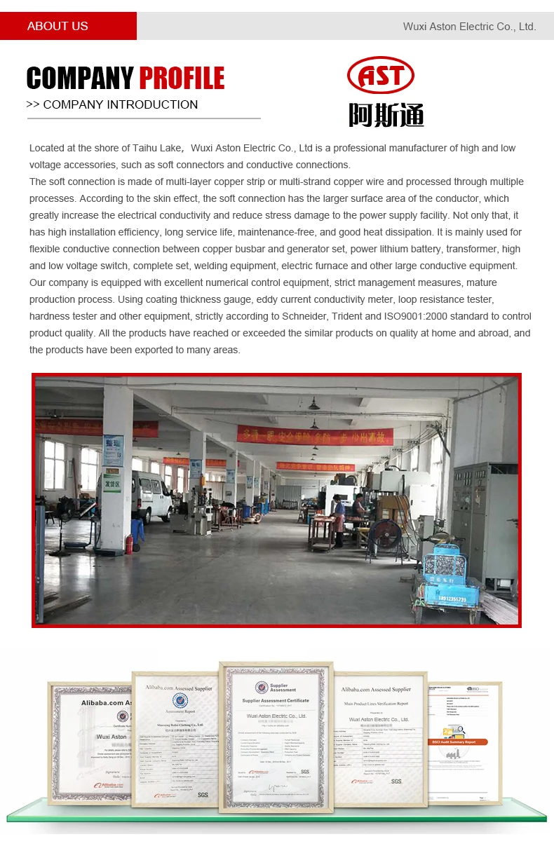
- Supplier: Wuxi Aston Electric Co. Ltd.
Share on (60835093264):
Product Overview
Description
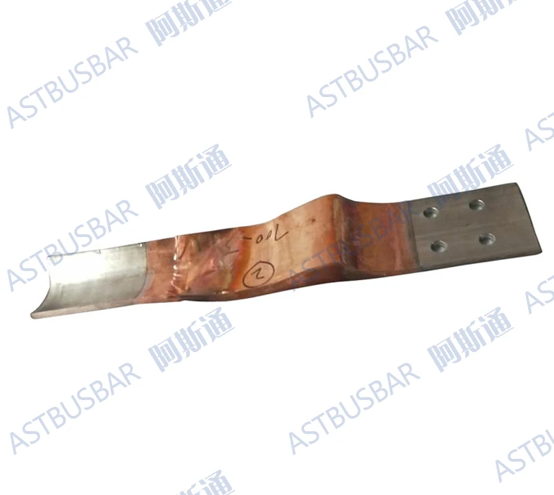
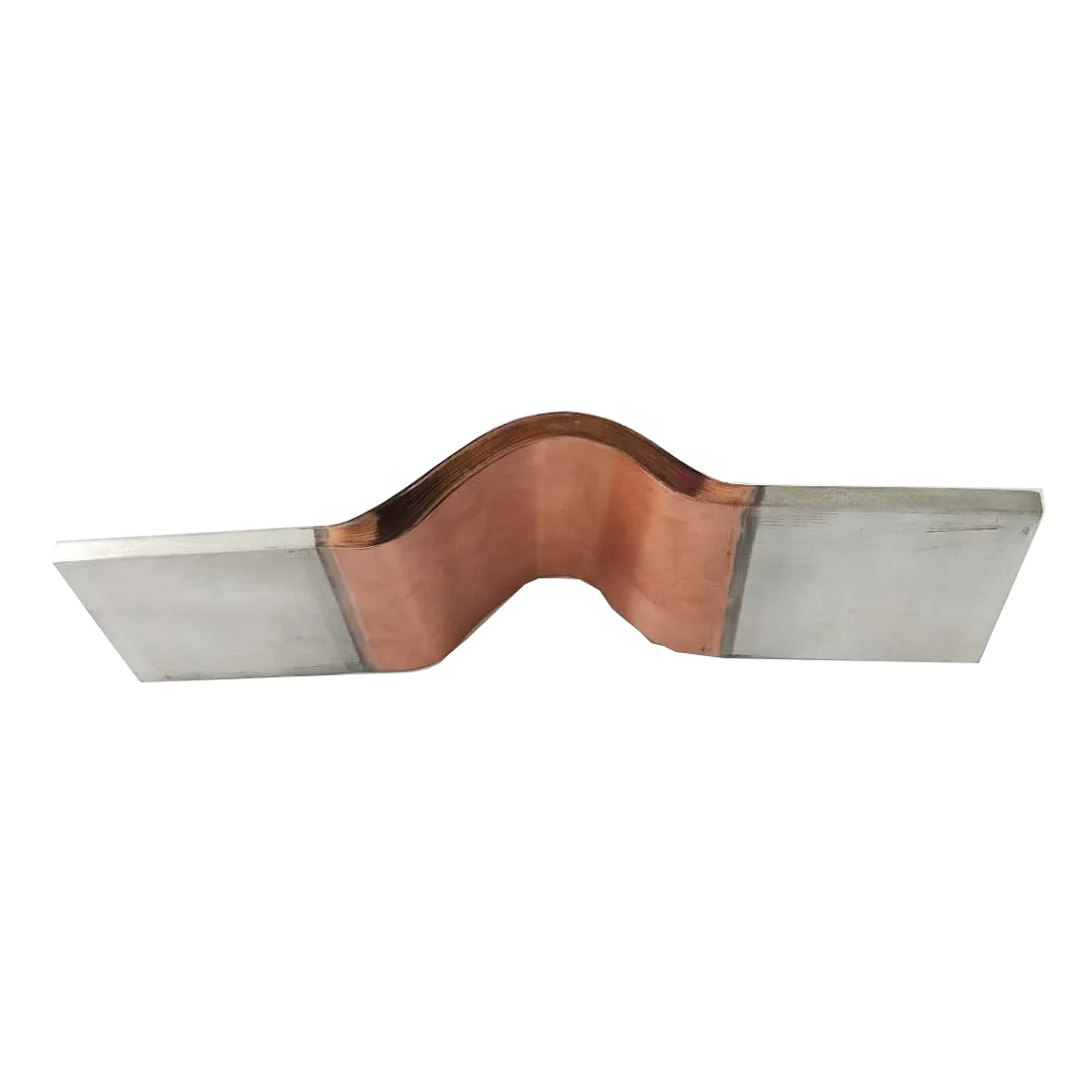
Flat copper busbar
Pressure welding soft conductor
The pressure welding is to press the copper foil laminations together, using molecular diffusion welding, and forming by high-current heating and pressure welding.
Copper foil: 0.03mm to 0.3mm thick.
The contact surface can be tinned or silver plated according to users’ requirements.
Description of pressure welding / brazing
In order to ensure the flatness of the contact surface,
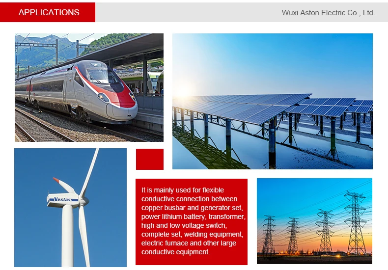
When A is greater than 90mm and B is greater than 60mm; use the contact surface paste copper friend (1mm thick) pressure welding process, see the scheme (I) shown in the figure.
When A is greater than 140mm and B is greater than 130mm: Brazing process is used, see the scheme (II) shown in the figure.
Technical parameters
See the table below.
The width, length and drilling holes not included in the table below can be processed according to user requirements.
The allowable current carrying capacity is a reference value. This value is related to the installation and use conditions of the soft connector.
Scheme (II)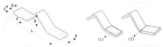
Technical parameter table of pressure welding / brazing
ED copper | Section mm2
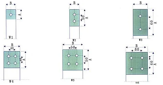
| A mm | B mm | S mm | L mm | H mm | Holes Diameter mm | End drilling | Current capacity A |
PWR 200/180/40 | 200 | 50 | 40 | 5 | 180 | 40 | 13 | W1 | 600 |
PWR 200/230/40 | 200 | 50 | 40 | 5 | 230 | 40 | 13 | W1 | 800 |
PWR 320/230/40 | 320 | 50 | 40 | 8 | 230 | 43 | 13 | W1 | 800 |
PWR 400/230/40 | 400 | 50 | 40 | 10 | 230 | 45 | 13 | W1 | 900 |
PWR 250/250/50 | 250 | 60 | 50 | 5 | 250 | 45 | 13 | W1 | 700 |
PWR 400/250/50 | 400 | 60 | 50 | 8 | 250 | 48 | 13 | W1 | 950 |
PWR 500/250/50 | 500 | 60 | 50 | 10 | 250 | 50 | 13 | W1 | 1100 |
PWR 480/300/60 | 480 | 90 | 60 | 8 | 300 | 70 | 13 | W2 | 1100 |
PWR 600/300/60 | 600 | 90 | 60 | 10 | 300 | 70 | 13 | W2 | 1200 |
PWR 640/300/80 | 640 | 90 | 60 | 8 | 300 | 70 | 13 | W4 | 1350 |
PWR 800/350/100 | 800 | 90 | 60 | 10 | 300 | 70 | 13 | W4 | 1500 |
PWR 960/300/80 | 960 | 90 | 60 | 12 | 300 | 70 | 13 | W4 | 1700 |
PWR 800/350/50 | 800 | 110 | 100 | 8 | 300 | 80 | 13 | W5 | 1550 |
PWR 1000/350/100 | 1000 | 110 | 100 | 10 | 350 | 80 | 13 | W5 | 1800 |
PWR 1200/350/100 | 1200 | 110 | 100 | 12 | 350 | 80 | 13 | W5 | 1900 |
PWR 1200/400/120 | 1200 | 130 | 120 | 10 | 400 | 80 | 13 | W7 | 2000 |
PWR 1440/400/120 | 1440 | 130 | 120 | 12 | 400 | 80 | 13 | W7 | 2200 |


We Recommend


New Arrivals
New products from manufacturers at wholesale prices


