Traffic flow based smart LED street lighting for energy optimization Energy Efficient Street Light System Use Traffic Adaptive
- Category: >>>
- Supplier: Guangzhou Cheng Hong E-Tech Co. Ltd.
Share on (1601164101500):
Product Overview
Description
Smart Traffic Management System:
Smart Traffic Management Systems are technology solutions that municipalities can integrate into their traffic cabinets and intersections today for fast, cost-effective improvements in safety and traffic flow on their city streets. What's more, deploying these systems today, or upgrading your city's existing Intelligent Transportation Systems (ITS) infrastructure can create huge efficiencies and cost savings, while massively improving system reliability, all of which have excellent ROI.
These systems utilize sensors, and automation lighting system to monitor and automatically direct traffic and reduce congestion. The right technology solution can be scaled to any size and painlessly upgraded at any time. Simultaneously, these technology solutions prepare Smart Cities Public Lighting Infrastructure for coming technology evolutions:Seamless Connected Vehicle and the full deployment of 4G/5G networks.
Smart LED Street light System Features:
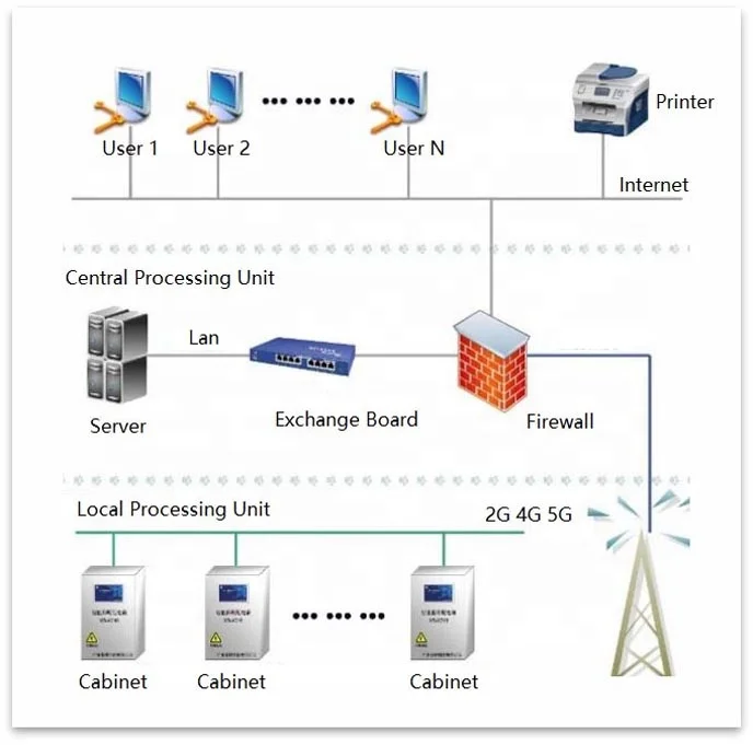
1. Server Capacity : Whole Country’s Projects can share 1 Server, Cloud Based Datahub
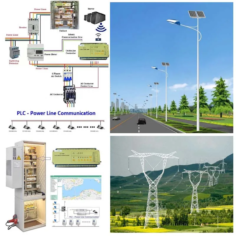
2. PLC Line Comm : PLC + LoRa with GSM/GPRS/3G/4G/5G
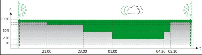
3. Automatic Run : Turn On/Off, Dimming according to the Nature Light Intensity/Ambient Light
4. Monitor Function: W/V/I/Tempt./Air Quality- PM2.5
5. Sensors Detect : Rain/Fog/Snow/Sunny/Cloudy/ Dimming according to Motion Sensor
6. Communication : Max. 2,000m
7. Auto-Reporting : Tempt/ Malfunctions/Loop Power
8. Grid/Metering : 3 phases Grid Data & Cabinet Monitoring / Power Consumption Report / Remote Energy Metering

II. Electrical Parameter
Item | Rating Range | |
Maximum Loading Lamp Qty. | 400 units(extend to1000 units, option for industry lighting) | |
Working Voltage | 120/240V±20%( Max.<420V) | |
Working Frequency | 50Hz - 60Hz | |
SwitchingOutput | 8A(MAX), Over-current Capacity (resistive load) | |
Insulation withstand voltage | 4KV, (RS485 interface and power supply) | |
Communication Channels | PLC, LoRa, or Hybrid of PLC + LoRa | |
Maximum Consumption Power | < 3 watts | |
Remote Control | Group & Individual ON/OFF/Dimming | |
Latitude & Longitude Switch | Yes | |
Lighting Sensors | Seamless Fill brightness by Illuminance Sensor + Motion Sensor | |
Scene Lighting Automatically | Rainy, Cloudy, Fogs, Snowing Days Auto-adjusting | |
Grid / Lamp Monitoring | V/I/W/PW, Active & Reactive Power, Lamp Tempt., Cabinet Door Status, Air quality PM2.5, Snow, Rain, Fogs etc. | |
Power Metering | Reporting & Analysis | |
GPRS Warning | Lamp Failure,Over Temperature/Voltage, Wires Stolen, GPS location the Stealing-electricity on google map. | |
Statistical Analysis | Luminance Ration, Alarm Statistics, Power Saving Ration, Voltage/Current Fluctuate, Environment Monitor | |
Protection | Automatic Shut down when Over Tempt. ; Location Stealing & Automatic Calculation of Power Stealing, Wire Stealing Alarm & Location, Decreasing Current Impact & Extend Lifetime. | |
Asset Management | Lower Budget can choose our Asset Managing System | |
Video Monitoring | CCTV Camera for safer city (option) | |
EV Charging | Option | |
Insulation withstand voltage | L/N-PE | 1.5KV |
L/N-485/DIM | 3.5KV | |
Surge Protect(L-N L-PE N-PE) | ±8KV | |
StaticElectricity | ±8KV | |
Operating Temperature | -25℃~+60℃ | |
Storage andWorkingHumidity | ≤85% | |
IP Rating | IP54 | |
Dimensions | 155x110*110mm (L/W/H) | |
Certifications | CE,ROHS | |
III: Key Features
1. Terminal Description

NO. | MARKS | Functions Description |
01 | IA+ | A Phase Current Sampling Interface + |
02 | IA- | A Phase Current Sampling Interface - |
03 | IB+ | B Phase Current Sampling Interface+ |
04 | IB- | B Phase Current Sampling Interface- |
05 | IC+ | C Phase Current Sampling Interface+ |
06 | IC- | C Phase Current Sampling Interface- |
07 | NC | Empty |
08 | UN | Power supplyNLine |
09 | UC | CommunicationcouplingC phase |
10 | UB | Communication couplingB phase |
11 | UA | Power supply/communication couplingA phase |
12 | RA1 | Power Supply StatusOutput Detect Port --In |
13 | RA2 | Power Supply StatusOutputDetect Port --In |
14 | RXD | RS232 Receiving Port |
15 | TXD | RS232 Sending Port |
16 | CGND | RS232 Common Port |
17 | COM | PowerPulseCommonPort |
18 | W | Active energy pulse output |
19 | Var | Reactive energy pulse output |
20 | GND | Power Supply StatusInputDetect Port - Common |
21 | IN1 | Power Supply StatusInputDetect Port - 1 |
22 | IN2 | Power Supply StatusInputDetect Port - 2 |
23 | 485B2 | RS485 Communication Port2 B |
24 | 485A2 | RS485 Communication Port2 A |
25 | 485B1 | RS485 Communication Port1 B |
26 | 485A1 | RS485 Communication Port1 A |
2. Indicator Description

3. Button Operation Instructions

1). Manual /Auto Run
Under Manual Status -The Dimming Button Operation on the panel is Effective, otherwise the operation is invalid.
Press the "Manual/Auto-Run" button to achieve manual / automatic state transition. That is to say, now it is Manual State, press again to enter the Auto-Run state.
When changing from Manual state to Automatic state, the equipment will automatically broadcast and issue Automatic Operation Recovery Command.
2). Controlling Button
No. | Button | Function |
01 | 100% | Send 100% dimming command to the selected loop |
02 | 75% | Send75% dimming command to the selected loop |
03 | 50% | Send50% dimming command to the selected loop |
04 | 25% | Send25% dimming command to the selected loop |
05 | Off | SendOff command to the selectedLoop (0% dimming) |
4. Lighting Controlling Functions
1). Control Priority Level
High priority or Same Level can change the state of low priority or same level, while low priority can not change the state of high priority.
The control mode corresponds to the following priorities.

2). Priority Level 1 - Recovery Auto-Run Operating (Highest Priority Level)
At this time, the state of priority Level 4 is executed regardless of the control state in which it was previously operated(the specific operation is performed according to the setting value at the time of installation).
a) The server or client remotely issues “Recovery Auto-Run” command.
b) Press the "Manual/Auto - Run" Button on the device panel
3). PriorityLevel2-LocalManualControl
Change the illuminance of the lamp through the control button on the device panel; at this time, the control commands of priority 3 and priority 4 will not be executed if the manual command is executed.
4). Priority Level 2-RemoteOperationControl
Remotely issue the controlCommands through the Server or the Client; at this time, the Lighting that executes theManual Command, the Priority Level 3 and Priority Level 4 control status will not be executed.
5). PriorityLevel3- IlluminationControl
Controls the Brightness values of all Fixtures according to preset rules by the received illuminance value.
6). PriorityLevel4 -Latitude&LongitudeControl
By setting the Latitude and Longitude values, the Sunrise and Sunset times are calculated, Disconnect the Loop at the sunrise time, Closed the Loop at the sunset time . The On-Off time can be fine-tuned by the Sunrise and Sunset offset time, and the range of fine-tuned for 30 minutes.
7). Priority Level 4 -ScheduleControl
Control the Brightness Value of the Fixture through the set 6-Segment Schedule.
5. DataCollection
Remote or Local Acquisition of Loop Controllers and Lamps Operating Status and Parameters.
6. ElectricalParameterAcquisition (Optional)
1).Collection ofElectricityConsumption
The device has a Built-in Three-Phase Energy Collection Module, which can collect the Energy Measurement Value of the Internal Module and Report it.
The Device can Collect the Energy Measurement Value of the Loop Controller and the Energy Meter and Report it.
2). ElectricalParameterAcquisition
The Built-in Three-Phase Energy Collection Module can collect the Voltage, Current, Active Power and Power Factor of the internal Module and Report it.
The Device can collect the Voltage, Current, Active Power and Power Factor of the Loop Controller, the Energy Meter and the Intelligent Lighting management Terminal, and Report it.
7. Fault Reporting
The Fault of the Device itself Occurs(AC Contactor Fault, Clock Fault, Communication Fault, etc.), and the Fault Information is automatically reported to the Server.
Collect the Information:such as Loop Controllers Fault and Light Controllers Fault, etc. (AC Contactor Faults, Clock Faults, Communication Faults, Lamp Faults, Temperature Faults, etc.)
8. DataCommunicationChannels
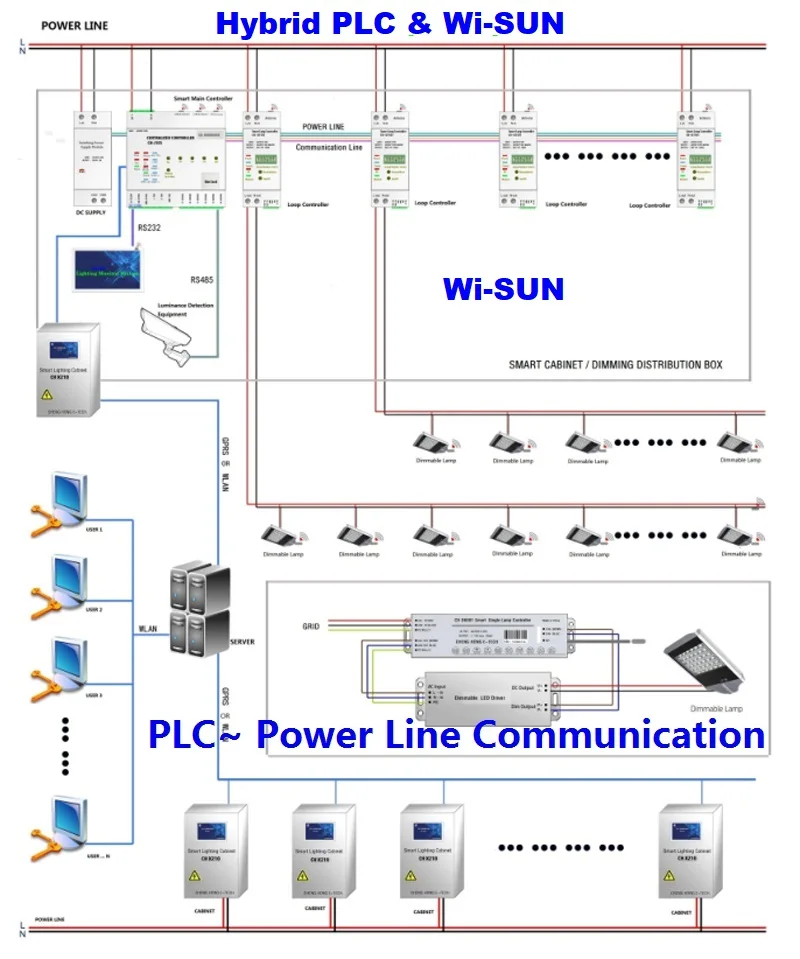
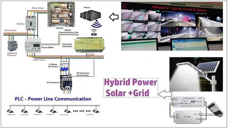
1) . PLC - Power Line Communication
Power Line Communication (PLC) is a communication technology that enables sending data over existing power cables. This means that, with just power cables running to an electronic device (for example) one can both power it up and at the same time control/retrieve data from it in a half-duplex manner.
2). LoRa Communication
Through LoRa Wireless Communication Channel, the Data Exchange and Control Command Reception between the Device and the Man-Machine Interface Device are realized. The Technical advantages are as follows:
a) Adopting the latest International IoT(Internet of Things) LoRaCommunication Technology, combined with AES128 Communication Encryption Technology and Self-Organizing Network Technology, the Communication Distance, Reliability and Security are greatly improved.
b) The Point-to-Point Communication Distance can reach 3,000m, and the measured average in the Power Plant is 1,000m.
c) In the case of Repeater, measured 13,000m can be normal communication.
3). RS-485 Communication
Through RS-485 Communication Channel, the Data Exchange and Control Command reception between the Device and the Man-Machine Interface Device are realized. The Technical Advantages are as follows:
a). The device capacity in the gateway is 255.
b). Strong Anti-Interference, Differential Mode Communication, and Software Fault Tolerance, no need to use Dedicated RS-485 Communication Line, reduce engineering cost under the premise of Ensuring Reliability
9. Extended Function (Optional)
1). Linkage
The Device can be linked with Equipment such as Cameras and Conveyer Belt; For example, when the Camera is activated, the Brightness of the Corresponding Lighting Area is Raised lighting the whole area, to Restore the Original Illumination when theCamera Stop Shooting; Another example, when the Conveyor Belt start transmission, its corresponding lighting area is adjusted the brightness, illuminates the area, and restores the minimum safe illuminance when Stop Transmission.
2). Dimming Loop Extension
The Control Loop can be concatenated to realize the application of Multiple Requirements.
VI: Soltutions-- PLC & LoRa

PLC ~ Power Line Communication

V: Widely application on the huge Projects


VI: Exhibitions Showing

We Recommend



New Arrivals
New products from manufacturers at wholesale prices