

CGD smart mirror anti fog bathroom mirror makeup mirror touch screen hand sweep sensor three stage stepless dimming switch
- Category: >>>
- Supplier: Foshan Chenggongda Intelligent Technology Co. Ltd.
Share on (1601250925488):
Product Overview
Description


Wiring Instructions
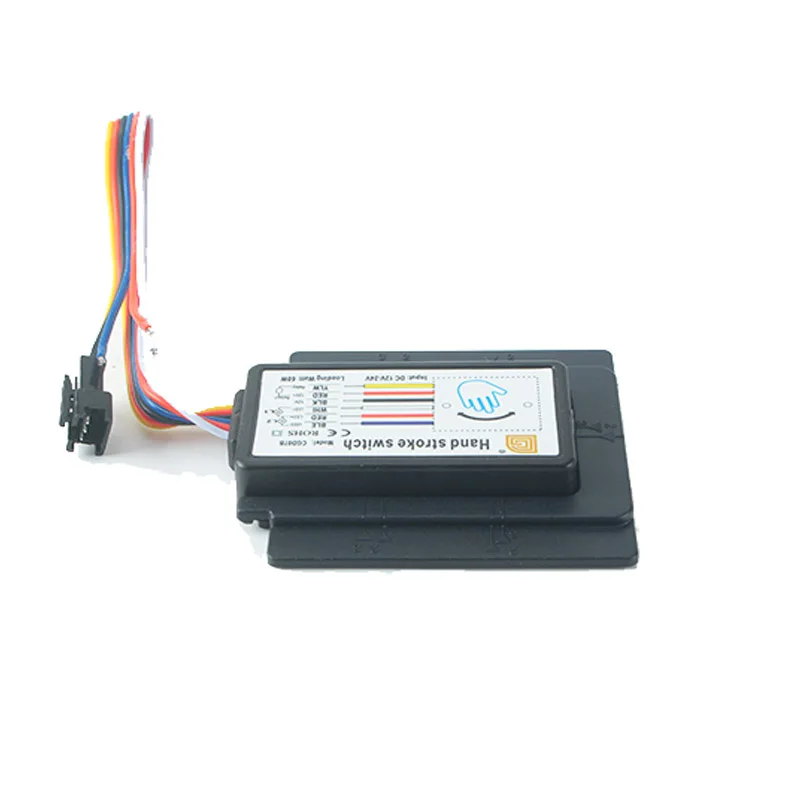
P R O U C T P A R A M E T E R S
1, THE YELLOW LINE IS THE RELAY OUTPUT LINE
2, RED, BLACK LINE FOR THE POWER INPUT LINE, RED FOR THE POSITIVE, BLACK FOR THE NEGATIVE
3, BLUE, RED, WHITE LINE FOR THE LED OUTPUT LINE, BLUE FOR LED2 NEGATIVE, RED FOR POSITIVE, WHITE FOR LED1 NEGATIVE
CGDO7B HAND SWEEP INDUCTION ELECTRODELESS DIMMER SWITCH WIRING INDICATION (EXTERNALRELAY)

CGDO7B HAND SWEEP INDUCTION ELECTRODELESS DIMMER SWITCH WIRING INDICATION (POWER BUILT-IN RELAY)

Installation instructions
P R O D U C T P A R A M E T E R S
1. Mirror laser marking illustration (on the back of the lens)

2.The back of the bracket is equipped with 3 Mglue Tear the backing
paper of the back 3 M glue and paste it on the corresponding marking
position on the back of the mirror according to the following method

The specific operation ofthe positioning frame is as follows:
First, the positioning plate is aligned with the marking position,and then the positioning frame is set on the positioning plate (as shown in Figure 4), and finally the positioning plate is removed from the right.
3. After the positioning frame is tightened, insert the host machine along the exit position of the positioning frame as follows


We Recommend


New Arrivals
New products from manufacturers at wholesale prices


